
Method and system for fabricating semiconductor components with through wire interconnects

a technology of through wire interconnection and semiconductor components, which is applied in the direction of semiconductor/solid-state device details, manufacturing tools, non-electric welding apparatus, etc., can solve the problems of low reliability, low electrical conductivity, and relatively high capacitan

Active Publication Date: 2006-10-12
MICRON TECH INC
View PDF44 Cites 161 Cited by
  • Summary
  • Abstract
  • Description
  • Claims
  • Application Information

AI Technical Summary

Benefits of technology

[0009] In accordance with the present invention, a method and a system are provided for fabricating semiconductor componen

Problems solved by technology

The disadvantages of via interconnects include a relatively low electrical conductivity, a relatively high capacitance, and a relatively low reliability, particularly with temperature cycling.
In addition, via interconnects can require expensive fabrication techniques, such as the filling of vias using seed and plating metallization equipment.

Method used


Image

  • Method and system for fabricating semiconductor components with through wire interconnects
  • Method and system for fabricating semiconductor components with through wire interconnects
  • Method and system for fabricating semiconductor components with through wire interconnects

Examples


Embodiment Construction

[0048] As used herein, “semiconductor component” means an electronic element that includes a semiconductor die, or makes electrical connections with a semiconductor die.

[0049] As used herein “wafer-level” means a process conducted on an element, such as a semiconductor wafer, containing multiple components.

[0050] As used herein “die level” means a process conducted on a singulated element such as a singulated semiconductor die or package.

[0051] As used herein “chip scale” means a semiconductor component having an outline about the same size as the outline of a semiconductor die.

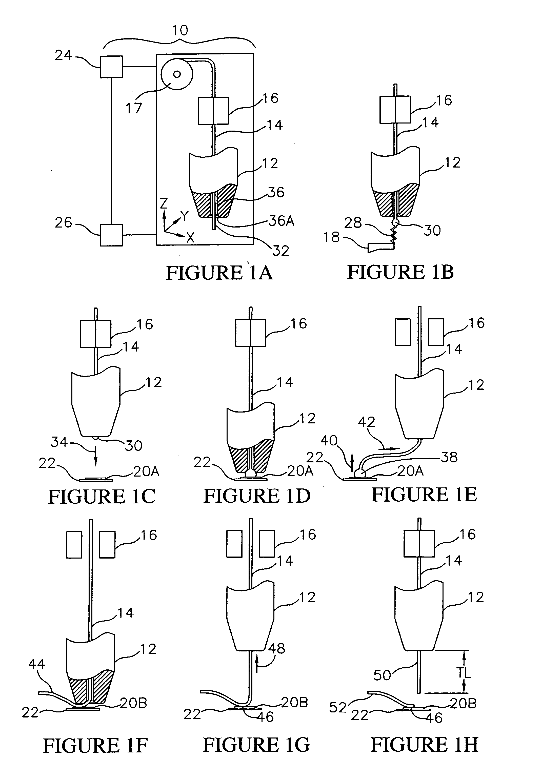
[0052] Referring to FIGS. 1A-1H, set up steps in the method of the invention are illustrated. For performing the method of the invention a wire bonder 10 (FIG. 1A) can be provided. Preferably the wire bonder 10 (FIG. 1A) is configured to perform an ultra fine pitch (e.g., <65 μm) wire bonding process. Suitable wire bonders are manufactured by Kulicke & Soffa Industries Inc. of Willow Grove, Pa., and SPT (...


PUM

PropertyMeasurementUnit
Thicknessaaaaaaaaaa
Capillary waveaaaaaaaaaa
Diameteraaaaaaaaaa

Abstract

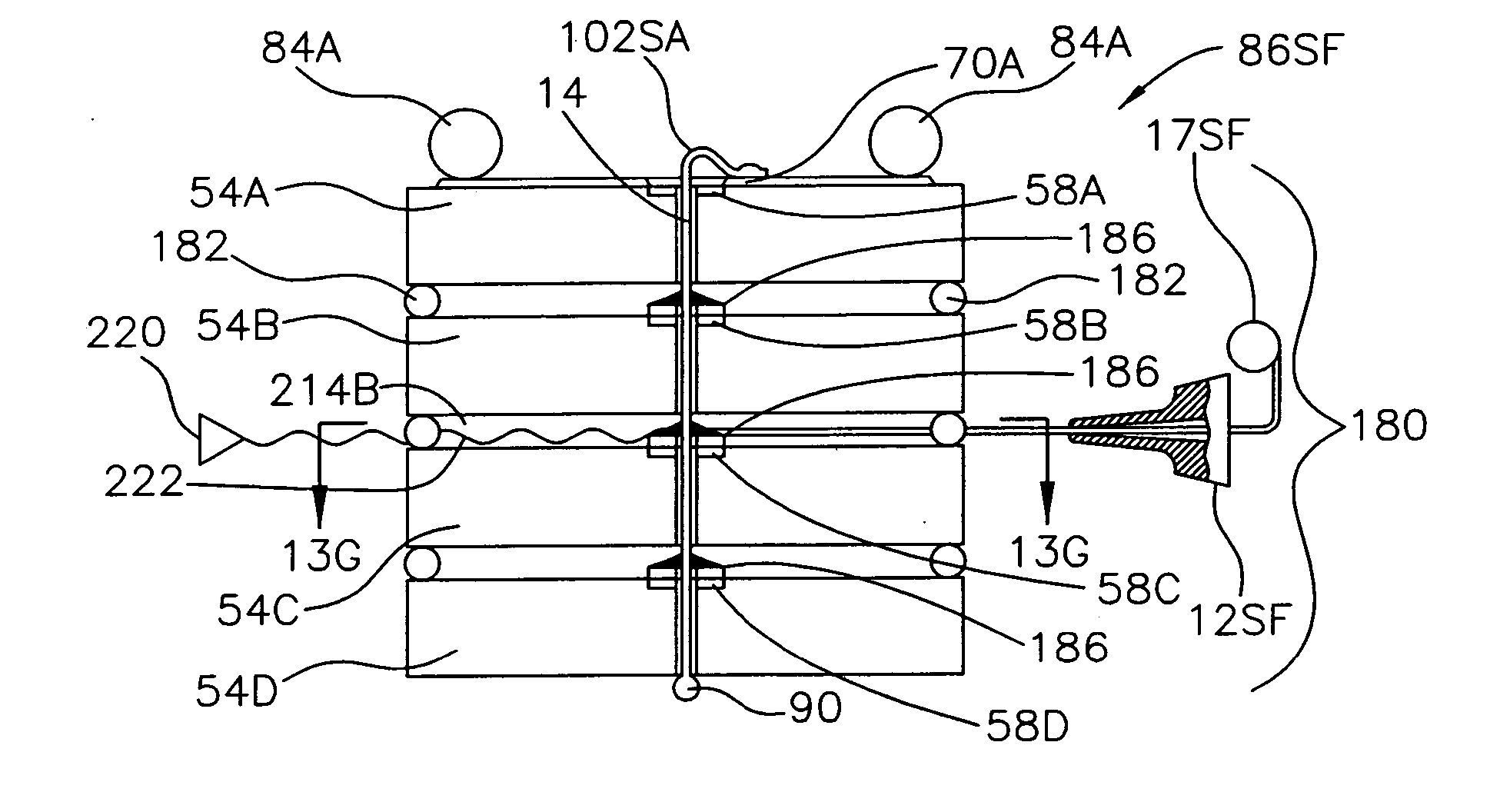
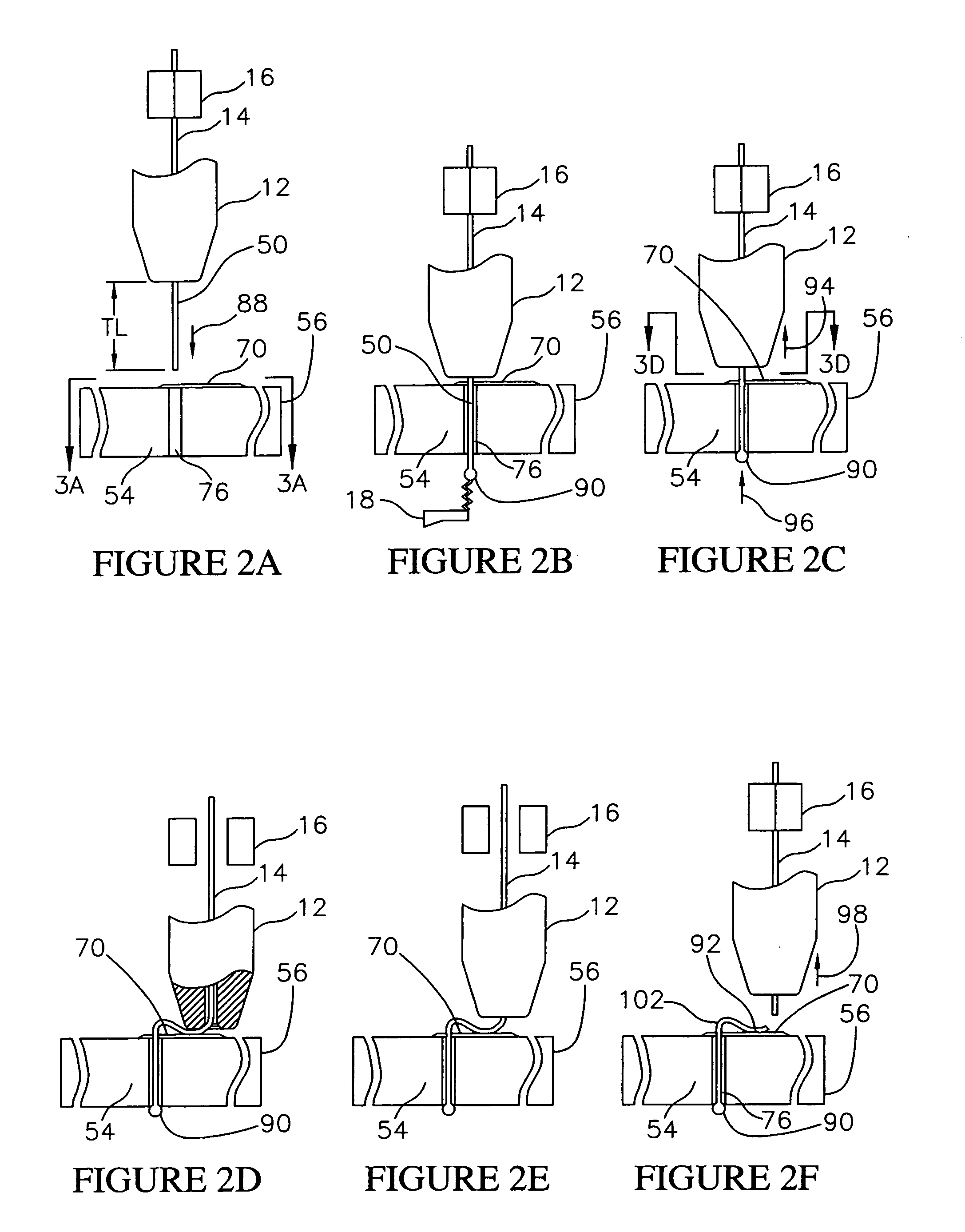
A method for fabricating a semiconductor component with a through wire interconnect includes the step of providing a substrate having a circuit side, a back side, and a through via. The method also includes the steps of: threading a wire through the via, forming a contact on the wire on the back side, forming a bonded contact on the wire on the circuit side, and then severing the wire from the bonded contact. The through wire interconnect includes the wire in the via, the contact on the back side and the bonded contact on the circuit side. The contact on the back side, and the bonded contact on the circuit side, permit multiple components to be stacked with electrical connections between adjacent components. A system for performing the method includes the substrate with the via, and a wire bonder having a bonding capillary configured to thread the wire through the via, and form the contact and the bonded contact. The semiconductor component can be used to form chip scale components, wafer scale components, stacked components, or interconnect components for electrically engaging or testing other semiconductor components.

Description

FIELD OF THE INVENTION [0001] This invention relates generally to semiconductor packaging, and particularly to a method and system for fabricating semiconductor components with through wire interconnects. This invention also relates to semiconductor components having through wire interconnects fabricated using the method and system. BACKGROUND OF THE INVENTION [0002] A semiconductor component includes a semiconductor substrate containing various semiconductor devices and integrated circuits. Typically, the semiconductor substrate comprises a semiconductor die, that has been singulated from a semiconductor wafer. For example, a chip scale semiconductor component includes a semiconductor die provided with support and protective elements, and an external signal transmission system. Semiconductor components can also include multiple semiconductor substrates in a stacked or planar array. For example, a system in a package (SIP) includes multiple semiconductor dice packaged in a plastic b...

Claims


Application Information

Patent Timeline
IPC IPC(8): H01L21/00
CPCB23K20/004B23K20/005H01L21/76898H01L23/481H01L23/49827H01L24/45H01L24/48H01L24/78H01L24/81H01L24/85H01L25/0657H01L25/50H01L2224/16H01L2224/45015H01L2224/45124H01L2224/45139H01L2224/45144H01L2224/45147H01L2224/45164H01L2224/4807H01L2224/48091H01L2224/4813H01L2224/48145H01L2224/48455H01L2224/48471H01L2224/48599H01L2224/48699H01L2224/78301H01L2224/8121H01L2224/81224H01L2224/81815H01L2224/85043H01L2224/85045H01L2224/85201H01L2224/85205H01L2224/85951H01L2225/06506H01L2225/06527H01L2225/06541H01L2225/06562H01L2225/06589H01L2225/06596H01L2924/01005H01L2924/01012H01L2924/01013H01L2924/01014H01L2924/0102H01L2924/01028H01L2924/01029H01L2924/01031H01L2924/01046H01L2924/01047H01L2924/0105H01L2924/01075H01L2924/01078H01L2924/01079H01L2924/01082H01L2924/014H01L2924/10329H01L2924/12044H01L2924/14H01L2924/19041H01L2924/20751H01L2924/20753H01L2924/20754H01L2924/20755H01L2924/20756H01L2924/20757H01L2924/20758H01L2924/20759H01L2924/2076H01L2924/30105H01L2924/3025H05K3/4046H05K2201/10287H05K2203/049H01L2224/9202H01L2924/01006H01L2924/01033H01L2924/01084H01L2224/45565H01L2224/48992Y10T29/49169Y10T29/49117Y10T29/49149Y10T29/53213Y10T29/49162Y10T29/49147H01L2924/00014H01L2924/20752H01L2924/00H01L2224/45644H01L2924/15787H01L2224/0557H01L2224/05573H01L2224/05571H01L2224/0554H01L24/03H01L2224/02379H01L24/05H01L2924/2075H01L2224/05599H01L2924/00012H01L2224/0555H01L2224/0556H01L23/48H01L21/00H01L21/02
Inventor HEMBREE, DAVID R.
Owner MICRON TECH INC
Learn More