Combined keyboard and wireless transceiver

a wireless transceiver and keyboard technology, applied in the field of computer systems, can solve the problems of reducing the useful life reducing the convenience and value of such devices, and reducing the range of wireless input devices, so as to reduce the number of transceivers, reduce the need for rf energy, and reduce the power drain of batteries

Inactive Publication Date: 2006-10-12
JAALAA
View PDF11 Cites 5 Cited by
  • Summary
  • Abstract
  • Description
  • Claims
  • Application Information

AI Technical Summary

Benefits of technology

[0016] In a first embodiment of the present invention a keyboard containing a transceiver is connected to a host computer, and a pointing device, e.g. a computer mouse, is coupled to the keyboard by means of RF transceivers in both the keyboard and the pointing device. The keyboard, having an affinity with the host computer and physically located in close proximity to the host computer, is connected to the host computer by an electrical connection comprising a USB or PS / 2 port. The pointing device, although used in close proximity to the host computer, is a moveable device in which wireless RF communications provides a freedom of movement unencumbered by an electrical connection. By connecting the keyboard to the computer with electrical means, an RF transceiver in the computer is eliminated thereby reducing the number of transceivers required as compared to the related patent applications. The pointing device (mouse) used in close proximity to the keyboard allows a reduction in the necessary RF energy transmitted by the keyboard and pointing device transceivers and in turn reduces the power drain on the batteries used to power the pointing device. No batteries are required in the keyboard to power the keyboard transceiver since the keyboard receives power from the computer.

Problems solved by technology

Batteries used to power existing wireless input devices typically last for a period of time significantly less than the useful life of such devices.
As a consequence, the convenience and value of such devices are diminished as a consequence of the need for regular battery replacement.
Wireless input devices are frequently of limited range, and the wireless link established for communication with the host computer can be unreliable and / or exhibit a high latency.
In addition, such wireless links can be relatively insecure and thus susceptible to eavesdropping or unauthorized monitoring.

Method used


Image

  • Combined keyboard and wireless transceiver
  • Combined keyboard and wireless transceiver
  • Combined keyboard and wireless transceiver

Examples


first embodiment

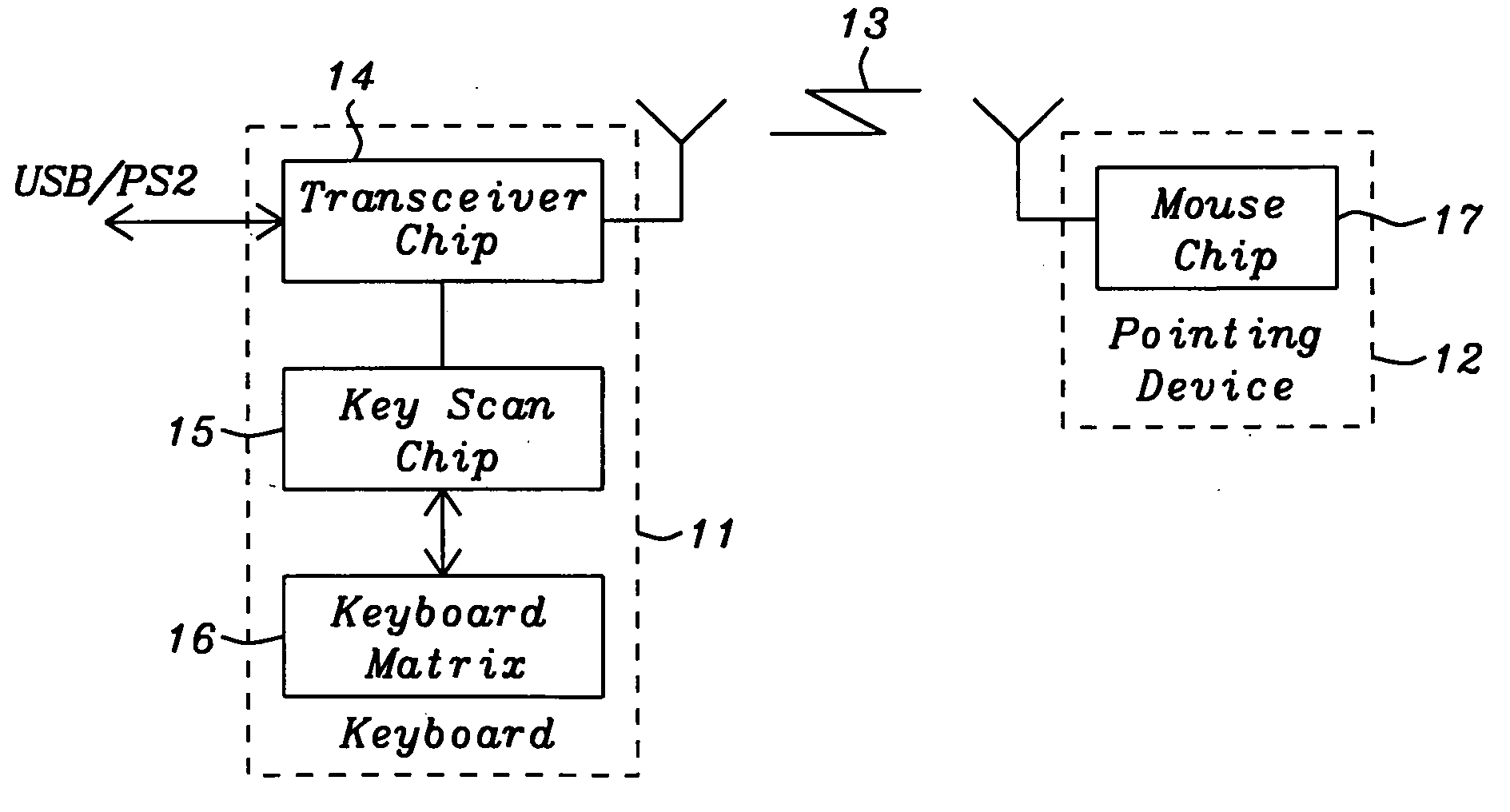
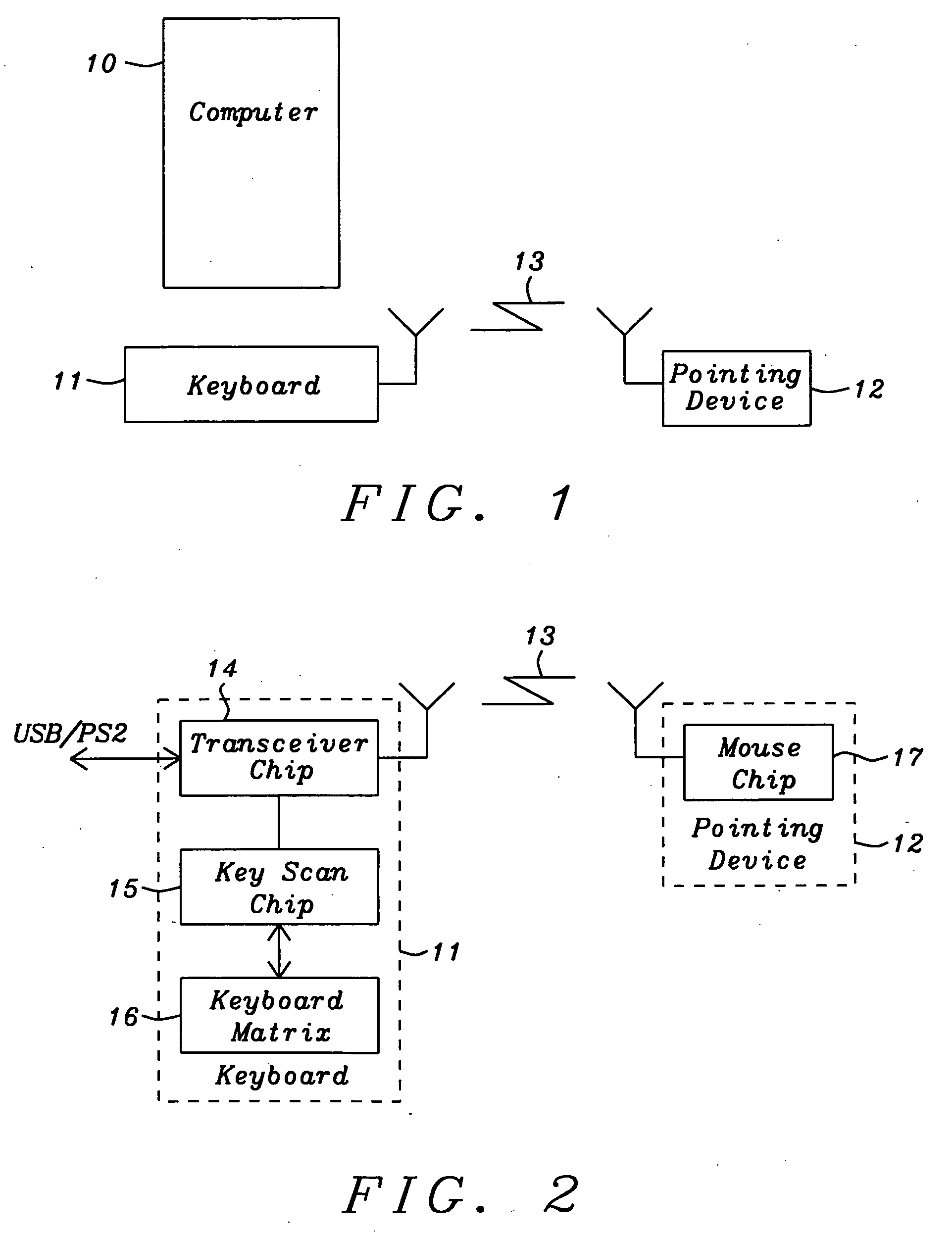
[0026]FIG. 2 is a block diagram of the present invention showing the keyboard 11 and the RF coupling 13 of a keyboard transceiver chip 14 to a mouse chip 17 in the pointing device 12. The keyboard transceiver 14 is coupled to a host computer 10 (FIG. 1) by means of an USB or PS / 2 connection. A key scan chip 15 used to detect the press and release of a key on the keyboard matrix 16 couples a signal representing the pressing and releasing of a key to the transceiver chip 14. The transceiver chip 14 sends a signal representing the pressed / released key to the computer 10 by means of the electrical connections. A CPU 20 (FIG.3) processes data from the key scan chip 15, for example to determine key mapping, and a modem 23 (FIG. 3) couples key press and release data to the computer 10 through the USB or PS / 2 ports. When the movement of the pointing device, for example a computer mouse, is detected, or an associated key on the pointing device is pressed, the mouse chip 17 detects the moveme...

second embodiment

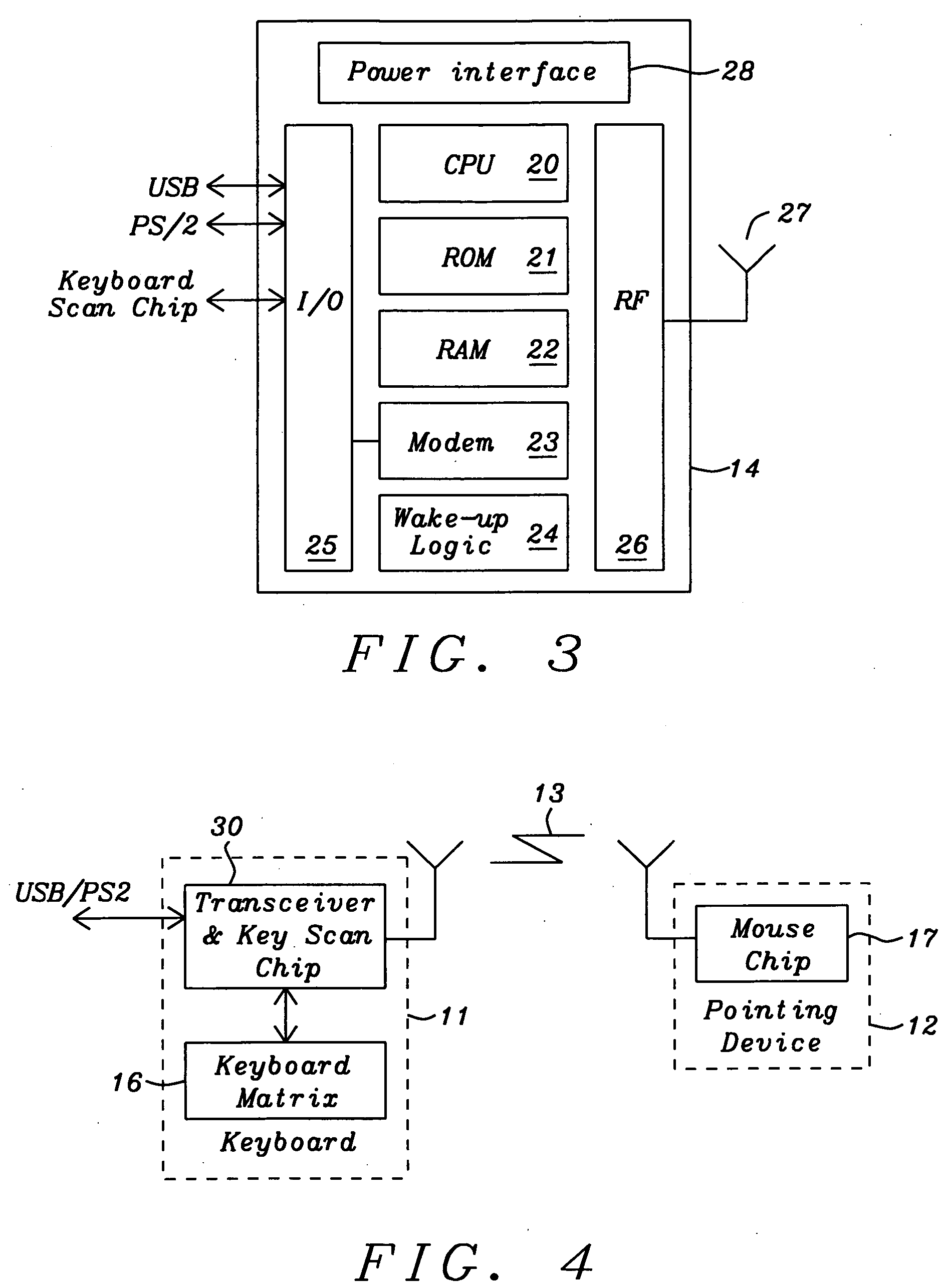
[0028]FIG. 4 shows a block diagram of the present invention. The diagram of FIG. 4 is similar to that of FIG.2 with the exception that the keyboard transceiver chip 30 includes the key scan function shown in FIG. 2 as a separate chip. The keyboard matrix 16 is directly coupled to the transceiver and key scan chip 30 where upon the key scan function detects key presses. The code for detected key press and release is coupled from the key scan function 30 to the transceiver function where a CPU 20 (FIG. 5) processes data from the key scan function, for example to determine key mapping, and the transceiver and key scan chip 30 couples to the host computer 10 (FIG. 1) key presses / releases on the keyboard 11 through the modem 23 (FIG. 5) to the USB or PS / 2 ports.

[0029]FIG. 5 is a diagram of second embodiment of the present showing the functions included in the keyboard transceiver and key scan chip 30. The diagram of FIG. 5 is substantially the same as that of FIG. 3 with the inclusion of...


PUM


Abstract

A wireless communication between a mouse and a keyboard connected to a computer with a cable provides a means for connecting mouse signals to a computer. Transceivers located in both the mouse and the keyboard provide RF communications that are converted by the keyboard transceiver to electrical signals to be coupled to the computer through USB or PS / 2 ports. An integration of a key scan function with a keyboard transceiver reduces the number of semiconductor chips required in the keyboard.

Description

[0001] This application claims benefit of U.S. Provisional Patent Application No. 60 / 669,261, filed on Apr. 7, 2005, which is herein incorporated by reference in its entirety. RELATED PATENT APPLICATION [0002] This application is related to U.S. patent application docket number JA 05-001A, Ser. No. 11 / 081,376, filed on Mar. 16, 2005; JA 05-001B, Ser. No. 11 / 081,380, filed on Mar. 16, 2005; JA 05-001D, Ser. No. 11 / 081,381, filed on Mar. 16, 2005; JA 05-002A, Ser. No. 11 / 082,009, filed on Mar. 16, 2005; JA 05-002B, Ser. No. 11 / 082,008, filed on Mar. 16, 2005; and JA 05-002D, Ser. No. 11 / 081,363, filed on Mar. 16, 2005.BACKGROUND OF THE INVENTION [0003] 1. Field of Invention [0004] The present invention relates generally to computer systems and, more particularly to an interface between a computer and input devices in communication with the computer over wireless links. [0005] 2. Description of Related Art [0006] Computers, microprocessor-based devices and systems have one or more user...

Claims


Application Information

Patent Timeline
Patent Type & Authority Applications(United States)
IPC IPC(8): G09G5/00
CPCG06F3/021G06F3/038G06F3/03543G06F3/0231
Inventor HSIEH, CHIH CHANGSINGAMSETTY, SURESH KUMAR
Owner JAALAA
Why Eureka
Try Eureka