Liquid storage container and liquid ejection recording apparatus having the container mounted thereon
- Summary
- Abstract
- Description
- Claims
- Application Information
AI Technical Summary
Benefits of technology
Problems solved by technology
Method used
Image
Examples
first embodiment
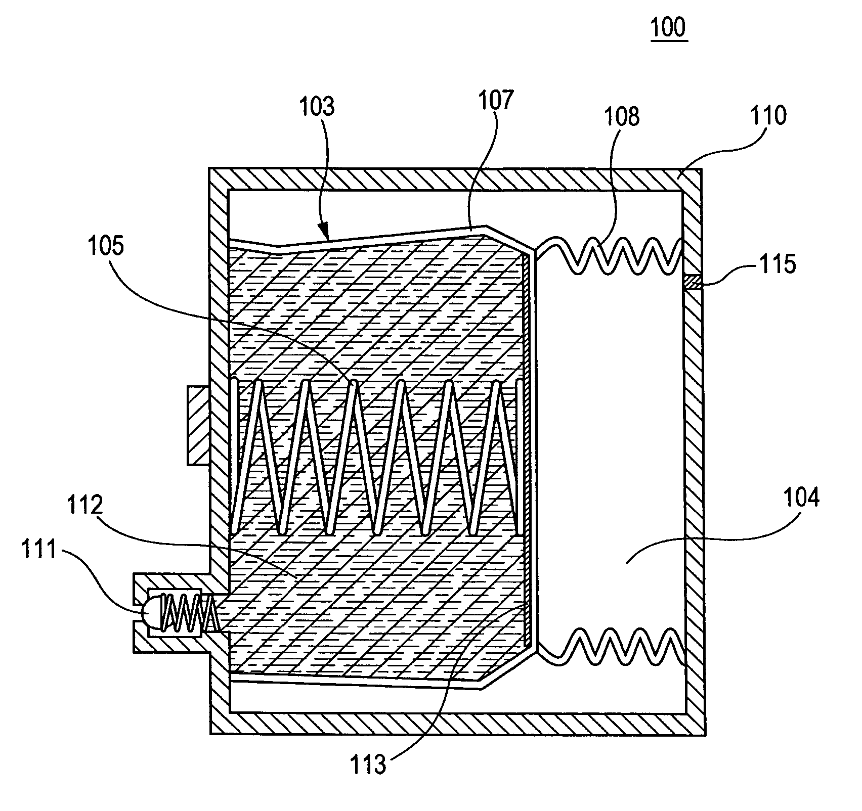
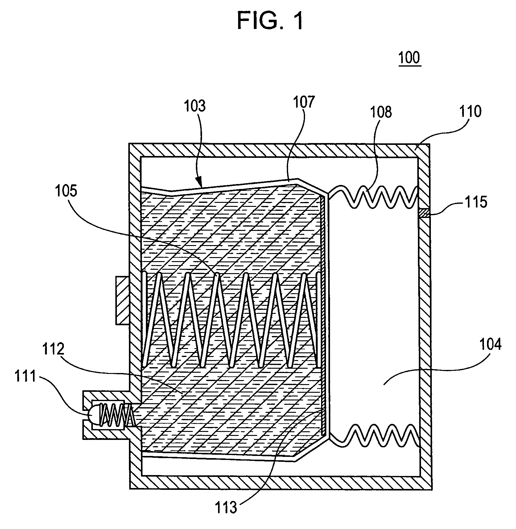
[0030]FIG. 1 is a sectional view of an ink cartridge according to a first embodiment of the present invention.
[0031] An ink cartridge (liquid container) 100 shown in FIG. 1 includes a hard casing 110 having an interior space and an ink supply port 111 formed on the wall of the casing 110 for supplying ink 112 (shown by reticular lines in the drawing) to the outside.
[0032] Within the casing 110, a film-like flexible bag 107 is accommodated for storing the ink 112 therein. The opening of the flexible bag 107 is joined onto the wall position where the ink supply port 111 is formed so as to form an ink reservoir 103. A sheet member 113 is provided on a portion of the flexible bag 107 opposing the wall position of the casing 110 where the ink supply port 111 is formed for flattening the portion. Between the wall position of the casing 110 where the ink supply port 111 is formed and the sheet member 113, a compression spring 105 is provided for urging the flexible bag 107 in a direction...
second embodiment
[0037]FIG. 2 is a sectional view of an ink cartridge according to a second embodiment of the present invention. Like reference characters designate like components common to the first embodiment.
[0038] An ink cartridge 200 shown in FIG. 2 includes the hard casing 110 having an interior space and the ink supply port 111 formed on the wall of the casing 110 for supplying the ink 112 (shown by reticular lines in the drawing) to the outside.
[0039] Within the casing 110, the film-like flexible bag 107 is accommodated for storing the ink 112 therein. The opening of the flexible bag 107 is joined onto the wall position where the ink supply port 111 is formed so as to form the ink reservoir 103. The sheet member 113 is bonded on a portion of the flexible bag 107 opposing the wall position of the casing 110 where the ink supply port 111 is formed for flattening the portion. Between the wall position of the casing 110 where the ink supply port 111 is formed and the sheet member 113, the com...
third embodiment
[0055]FIG. 4 is a sectional view of an ink cartridge according to a third embodiment of the present invention. An ink cartridge 300 according to the embodiment has basically the same configuration and operation as those of the second embodiment, and so description thereof is omitted.
[0056] The point in which the third embodiment differs from the second embodiment is that the electric contact block 102 for electrifying the shape-memory alloy wire 101 is arranged on a surface different from that of the casing 110 where the ink supply port 111 is provided. Thus, the shape-memory alloy wire 101 is folded to the interior of the casing 110 at a fulcrum 116 arranged in the vicinity of the wall of the casing 110 where the ink supply port 111 is formed.
[0057] According to the embodiment, an electrical defect can be prevented, which might be caused by the adhesion of ink leaked from the ink supply port 111 for supplying the ink to the exterior by some reason.
Other Embodiments
[0058] Then, ...
PUM
 Abstract
Description
Claims
Application Information
 - R&D
- Intellectual Property
- Life Sciences
- Materials
- Tech Scout
- Unparalleled Data Quality
- Higher Quality Content
- 60% Fewer Hallucinations
Browse by: Latest US Patents, China's latest patents, Technical Efficacy Thesaurus, Application Domain, Technology Topic, Popular Technical Reports.
© 2025 PatSnap. All rights reserved.Legal|Privacy policy|Modern Slavery Act Transparency Statement|Sitemap|About US| Contact US: help@patsnap.com


