
Methods and apparatus for maintaining a map of node relationships for a network

a network and node technology, applied in the field of network node relationships maintenance methods and apparatus, can solve the problems of network administration nodes being burdened by repeated communications, /or the status information regarding other nodes becoming out of date,

Inactive Publication Date: 2006-09-28
CISCO TECH INC
View PDF27 Cites 162 Cited by
  • Summary
  • Abstract
  • Description
  • Claims
  • Application Information

AI Technical Summary

Benefits of technology

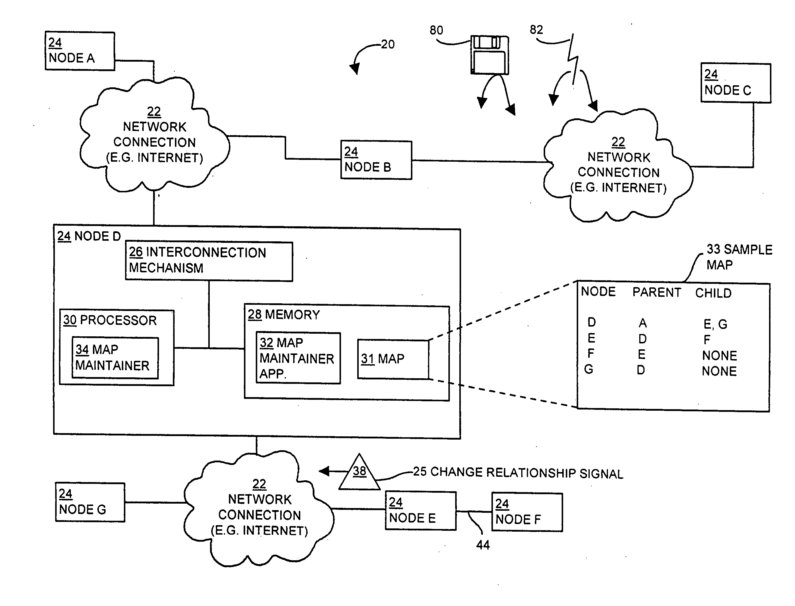
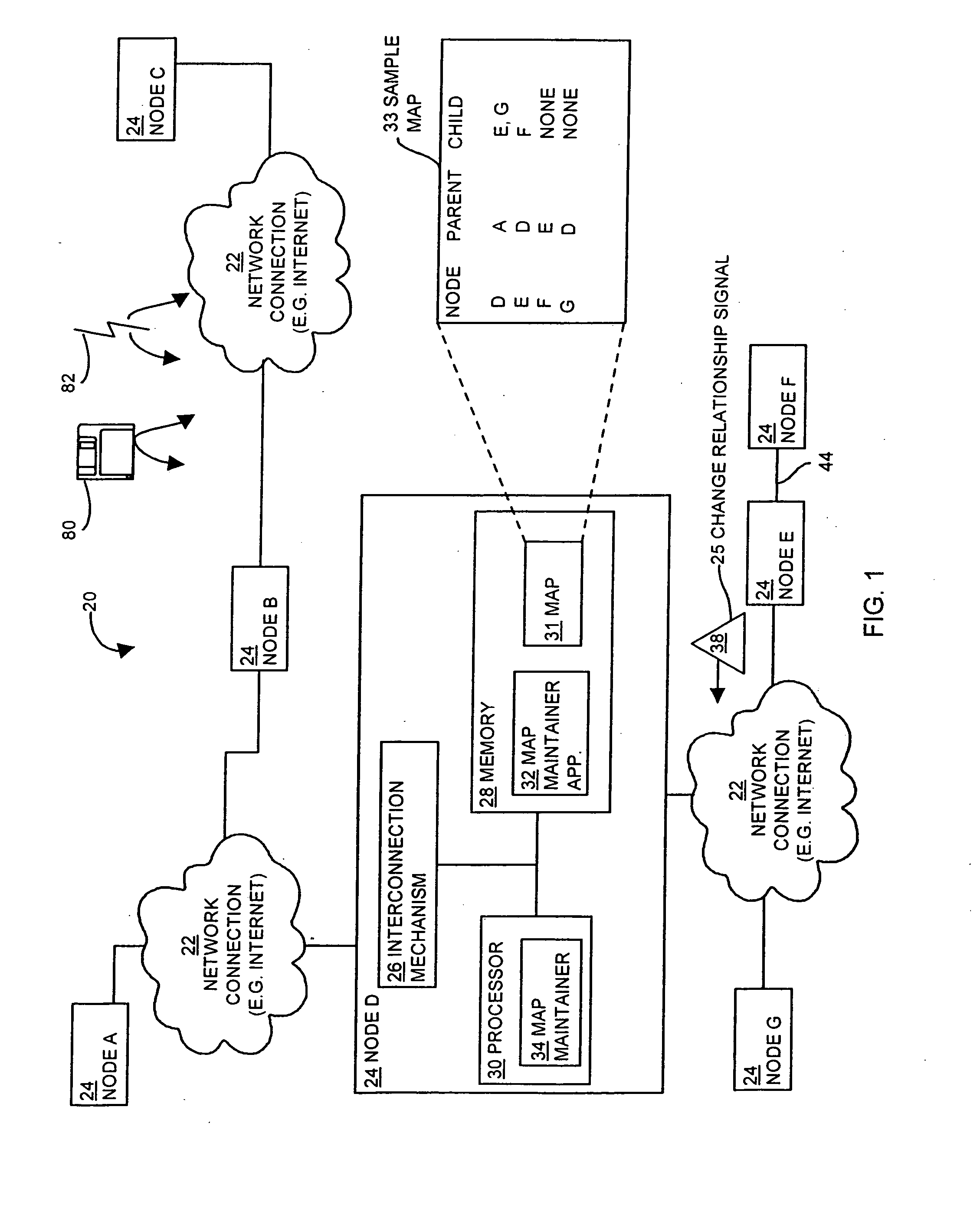
[0009] More specifically, in the approach of the invention, nodes (e.g. computers in a network) in relationships with other nodes in a network, node tree or graph, maintain maps of the relationships. The relationships may represent physical connections among nodes that are computers or other networked devices or logical relationships in an overlay network, in which the logical relationships among nodes in the overlay network typically do not conform to the physical connections among the computers (e.g., the logical relationships represent virtual connections). The nodes in the network propagate change information (e.g., change relationship signals) up the node tree. For example, the node tree includes a root node that may be connected to several nodes in the tree, which are parent nodes to lower level nodes (i.e., child nodes). The root node receive change information (e.g., information conveying a node relationship change), and the nodes in the tree can filter out redundant or unnecessary change information so that higher level nodes and the root only receive a minimal amount of information and are not overwhelmed with a large number of change relationship communications from every node in the node tree.
[0011] The relationships of interest can be physical connections (e.g., connection or disconnection of a physical cable connecting to the network), data communication links (e.g., establishment or termination of a TCP connection over a physical network) or virtual connections (e.g., creation or destruction of a hyperlink over the web). If a node is unable to communicate with another node (e.g., a parent of that node) or the computer for the node has shut down, then the logical relationship to that node may be unavailable. Thus, the root node is not overwhelmed in a very large network (e.g., thousands of nodes) with receiving many creation and termination signals communicated directly to the root node of many disconnections or connections of a large number of child nodes.
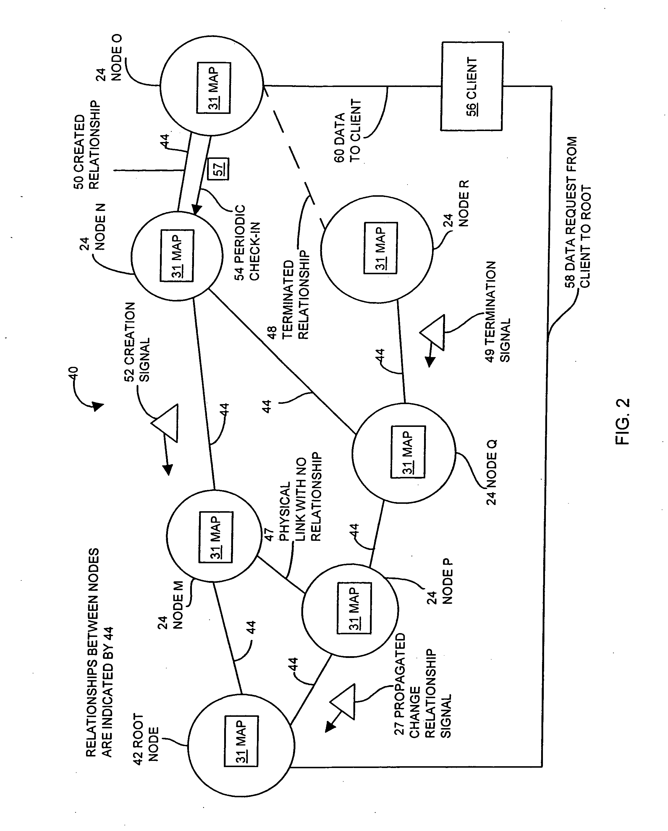
[0012] In one environment suitable for use with the invention, a root node provides content that is broadcast (e.g., “overcast”) over nodes in a network, such as video data broadcast over a group of nodes in the Internet. In the approach of the invention, a root node maintains a map of the nodes in the group. Nodes in the network may change their relationships, for example, to optimize pathways through the network so as to dynamically optimize the efficiency of the network. If nodes move in the network, the root receives termination signals and / or creation signals that represent change information, and uses this change information to update the root's map of the network.
[0013] The root uses the map when communicating with a client. For example, if a client wishes to receive content (e.g., video) from the root, the root directs the client to attach itself (i.e., to form a data communications connection with) as a child node to one of the nodes (now acting as a parent node) in the network. The root can rely on the change information that it has been maintaining to choose a parent node for the client that has an active pathway from the root to the parent node. The root can then broadcast the content (e.g., video) throughout the network. Thus, from its map, the root has reliable, recent information on the status of nodes in the network that allows it to choose a reliable pathway between the root and the client. The client can receive the content reliably without being required to investigate the status of every node in the pathway to the root. In addition, the techniques of the invention allow the root to use a very large network with reliable status information so that content information can be reliably provided to a very large number of clients, using many pathways through the network so that many clients can receive the content without any substantial performance degradation.
[0023] In an additional embodiment, the method includes initiating a check-in communication from the second network node to the first network node. Thus, the child node initiates the communication with the parent and provides a report that reflects the child's status and any propagated change relationship signals from lower level nodes. This approach has the advantage of allowing child and lower level nodes to be located behind a firewall that the parent node cannot penetrate (e.g., cannot send signals through) and the parent node is not required to proactively contact each of its child nodes to determine its status and relationships.

Problems solved by technology

These repeated communications can be a burden on the network administration node, especially for very large networks, such as the Internet, or other networks with a large number of nodes.
The network administration node or other monitoring node may be burdened by repeated communications to the point that performance of this node or the network declines and / or the status information regarding other nodes becomes out of date.
However, such changes may not be automatically relayed to other nodes on the network, even in the case of other nodes that a client communicates with frequently.

Method used


Image

  • Methods and apparatus for maintaining a map of node relationships for a network
  • Methods and apparatus for maintaining a map of node relationships for a network
  • Methods and apparatus for maintaining a map of node relationships for a network

Examples


Embodiment Construction

[0045] The invention is directed to techniques for maintaining a map of relationships among nodes in a network (or graph), in which the nodes are computers or network devices in a network of physical connections or logical relationships overlaying the physical connections of the network. Each node monitors or otherwise detects changes in relationships among lower level nodes (e.g., one or more child nodes in a node tree). The node may receive a signal indicating that the relationship has changed (e.g., a change relationship signal). The change may be a creation of a new relationship, such as when a child attaches itself to a new parent, or a termination of a relationship, such as when a child ends a relationship with the previous parent. A map maintainer in each node maintains a map of node relationships for nodes (e.g., nodes below the node in a node tree) and updates the map when the node receives information on a change in relationships among the nodes. If the node receives appar...


PUM


Abstract

The invention is directed to techniques for maintaining a map of node relationships for a network of nodes (e.g., network of computers). In one example, the map of node relationships represents relationships overlaying and typically different from the network of physical connections among the nodes. Each child node periodically checks in with its parent nodes, and the parent nodes can thus determine when a child node has terminated a relationship with the parent or created a new relationship with a new parent. Changes in relationships propagate upward through the network of nodes so that each node maintains a map of the relationships among the descendants of that node. A root node receives the propagated change relationship information and maintains a map of the entire network and valid pathways through the network. The root node can use the map when responding to a request from a client to receive services from a node in the network and redirects the client to attach to a node in the network that has a valid path to the root node. The root node can then broadcast data (e.g. a stream of video data) throughout the network, which is received by all the clients attached to nodes in the network.

Description

CROSS REFERENCE TO RELATED APPLICATIONS [0001] This application is a divisional of U.S. patent application Ser. No. 09 / 752,842 filed Dec. 29, 2000, which is a non-provisional of U.S. Provisional Patent Application No. 60 / 177,985, filed Jan. 25, 2000, entitled “Fast Changing Network Status and Load Monitoring and Feedback,” the disclosure of which is incorporated in its entirety herein by reference.BACKGROUND OF THE INVENTION [0002] Historically, computers communicated over dedicated communication lines or through specific connections such as a modem connection from one computer to another. Computers have also been connected in networks that allow communication among a number of computers. If a computer is added or removed from the network, typically a human operator notifies a dedicated network application of the addition or removal. In another conventional approach, a specialized network administration node tracks the changes to the network. [0003] In a modern network, such as the ...

Claims


Application Information

Patent Timeline
IPC IPC(8): G06F15/173
CPCH04L12/185H04L41/12H04L45/02H04L45/04
Inventor O'TOOLE, JAMESJANNOTTI, JOHN J.
Owner CISCO TECH INC
Learn More