
Radio frequency power amplifier and corresponding method

a radio frequency power amplifier and power supply technology, applied in the direction of amplifiers with negative feedback circuits, amplifiers with semiconductor devices/discharge tubes, etc., can solve the problems of difficult or impossible to accurately receive/demodulate signals, battery size and hence weight and cost increase directly with power requirements,

Inactive Publication Date: 2006-09-28
PWRF
View PDF14 Cites 12 Cited by
  • Summary
  • Abstract
  • Description
  • Claims
  • Application Information

AI Technical Summary

Problems solved by technology

Small distortions in the form of the output signal relative to the input can cause the radio frequency power amplifier to interfere with other radio services, in violation of regulatory requirements, or make it difficult or impossible to receive / demodulate the signal accurately.
These distortions may be caused, for example, by the fact that the characteristics of the components of which a radio frequency power amplifier is composed (e.g. transistors) are non-ideal, e.g., vary with the electrical currents that they carry, which necessarily include the signal being reproduced.
The power (90 Watts in the example) “wasted” in this way causes many problems.
When equipment is battery-operated (e.g. in cell phones or in fixed installations (base transmitters) that are running on backup batteries during a power failure), battery size and hence weight and cost increases directly with power requirements.
However, class E amplifiers pose problems.
For example, since there output power is effectively set by a power supply voltage, they are difficult to amplitude-modulate and attempts to do so have resulted in both poor efficiency and poor linearity.
The inability to modulate amplitude severely limits applicability of the class E amplifiers in most modern systems employing complex forms of modulation with varying amplitude or amplitude inverting signals.
In practice, since Class D amplifier are continually discharging capacitance (e.g., when turned on) and this can amount to significant power dissipation at radio frequencies.
This causes problems for class E radio frequency power amplifiers since their inputs need to be synchronized with a high frequency signal.

Method used


Image

  • Radio frequency power amplifier and corresponding method
  • Radio frequency power amplifier and corresponding method
  • Radio frequency power amplifier and corresponding method

Examples


Embodiment Construction

[0019] In overview, the present disclosure primarily concerns communication equipment including radio frequency transmitters or amplifiers such as used in infrastructure equipment including base stations or in communications units. Such radio frequency amplifiers for example, may be found in cellular, two-way, and the like radio networks or systems in the form of fixed or stationary and mobile equipment. The fixed equipment is often referred to as base stations or transmitters and the mobile equipment can be referred to as communication units, devices, handsets, or mobile stations. Such systems and equipment are normally used to support and provide services such as voice and data communication services to or for such communication units or users thereof.

[0020] More particularly various inventive concepts and principles are embodied in systems or constituent elements, communication units, transmitters and methods therein for providing or facilitating radio frequency amplifiers or po...


PUM


Abstract

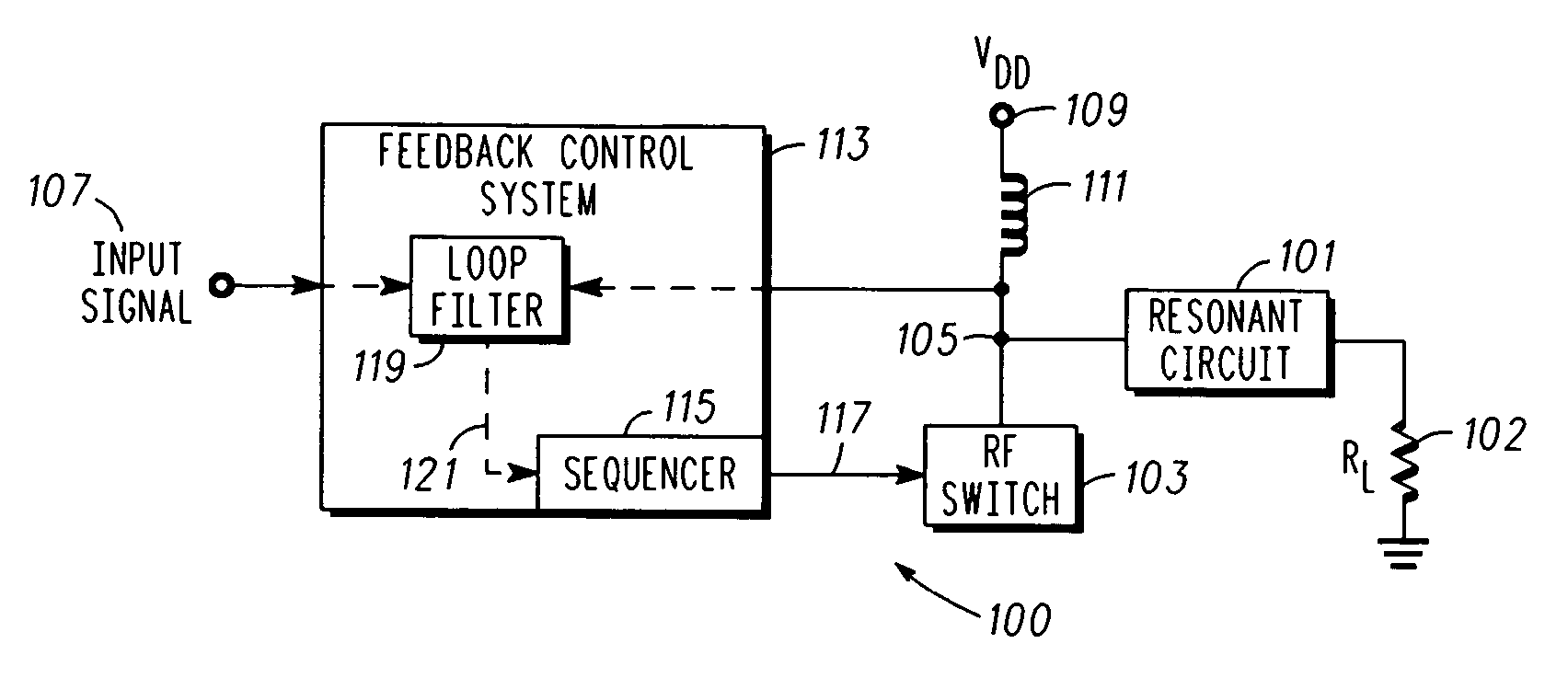
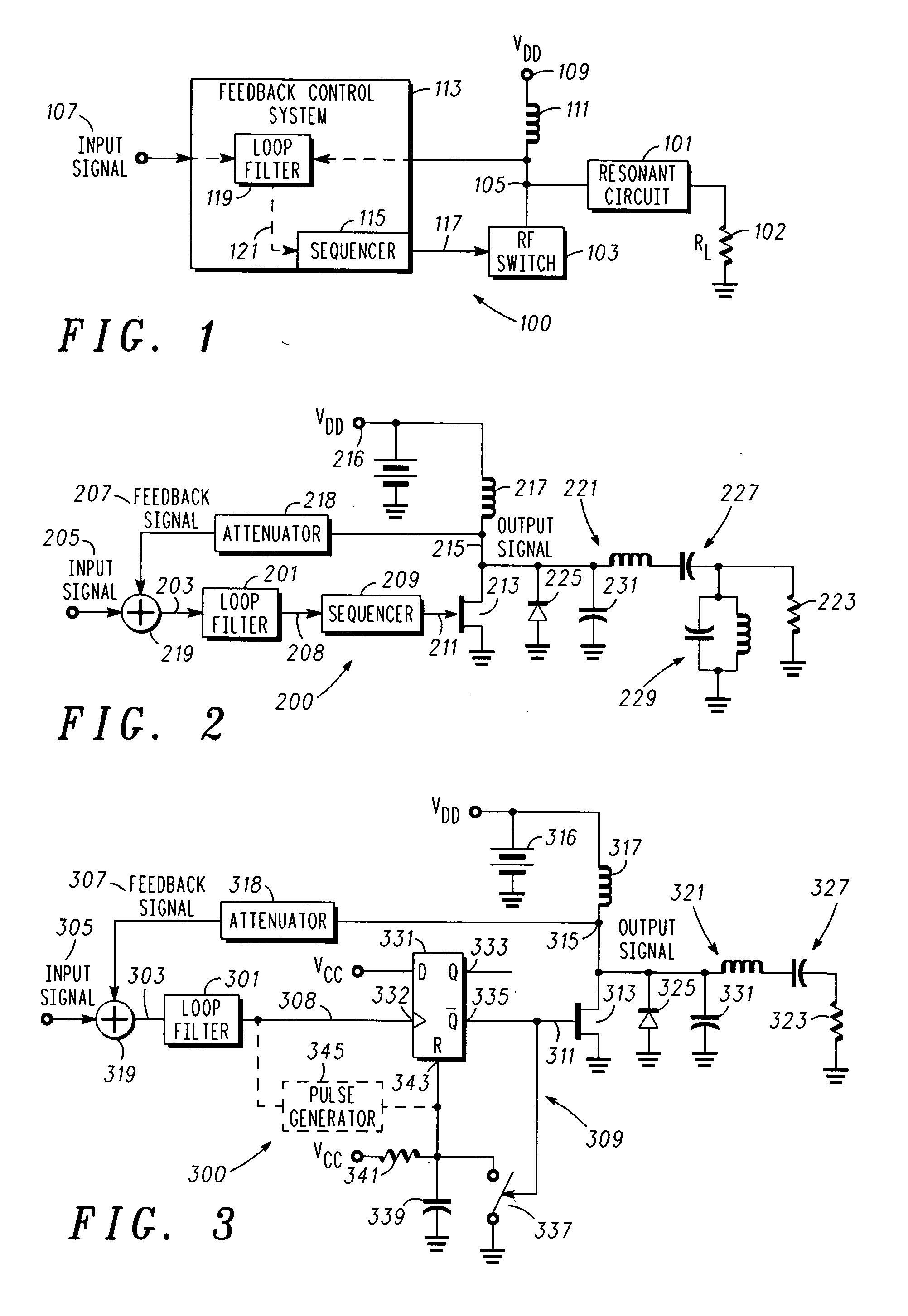
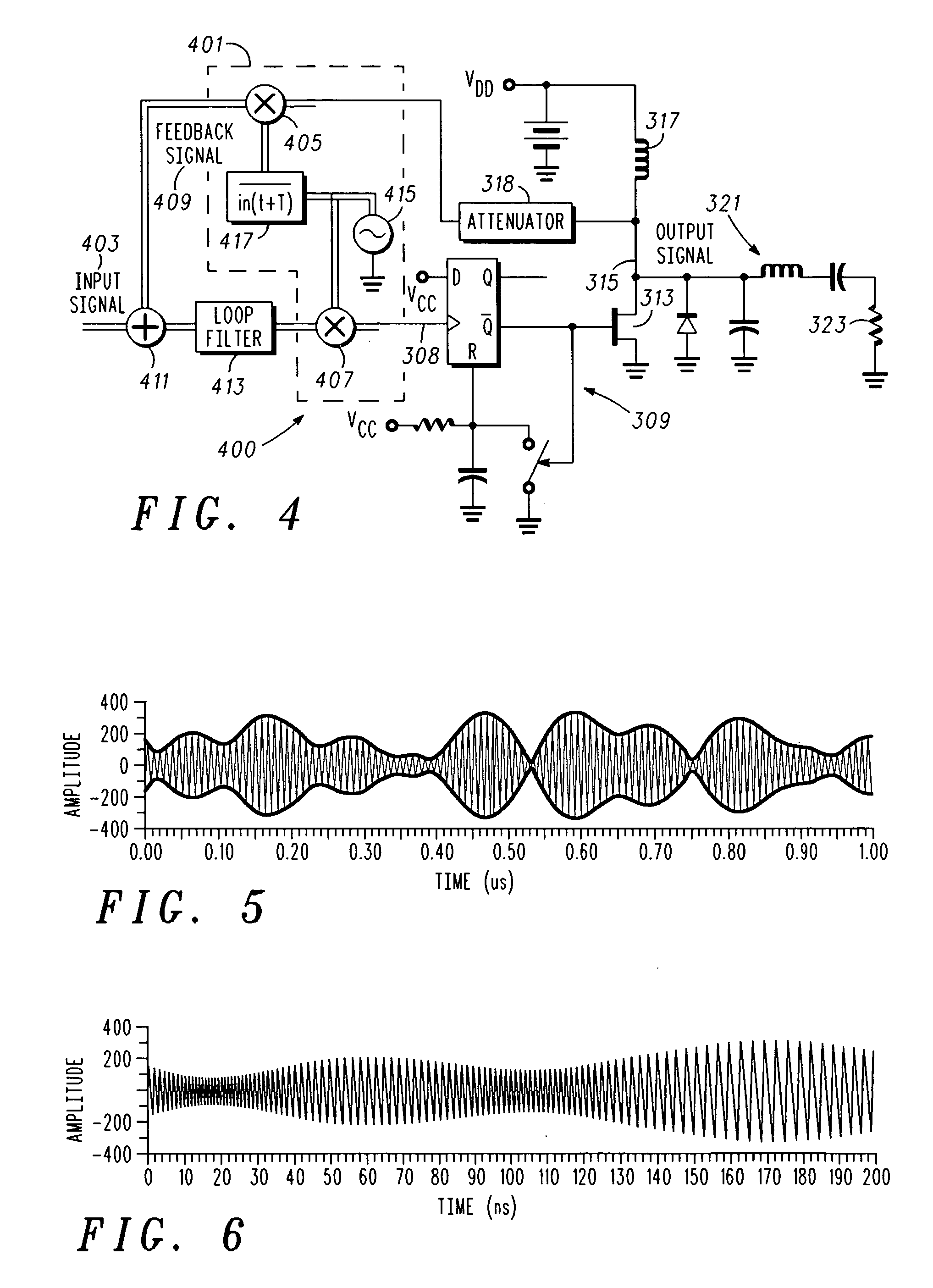
A radio frequency power amplifier and corresponding methods are arranged and configured to drive or provide a radio frequency signal to a resonant load. The amplifier includes a radio frequency switching stage with an output that is coupled to a resonant circuit and configured to provide an output signal with amplitude modulation corresponding to amplitude modulation of an input signal when powered from a fixed voltage power supply and a feedback control system coupled to the input signal and the output signal. The feedback control system includes a sequencer configured to provide a sequencer output that is used to drive the radio frequency switching stage, where the sequencer output has an OFF state that begins at a variable time corresponding to the input and output signal.

Description

FIELD OF THE INVENTION [0001] This invention relates in general to communication equipment, and more specifically to radio frequency power amplifiers. BACKGROUND OF THE INVENTION [0002] Radio-frequency power amplifiers are essential components of transmitters found in radio communication systems, and are deployed in various applications, such as mobile telephony, broadcast, wireless data networking, radiolocation and other fields. Generally, they function to make copies of their inputs, which are signals generated by other components of communication equipment, such as base transmitters, mobile devices, or the like, where the copies or output signals are powerful enough to propagate for appropriate distances. Two often conflicting requirements that constrain radio frequency power amplifiers are linearity and efficiency. [0003] The linearity requirement or constraint on a radio frequency power amplifier is that it reproduces the form of its input signal faithfully. Small distortions ...

Claims


Application Information

Patent Timeline
Patent Type & Authority Applications(United States)
IPC IPC(8): H04B1/04
CPCH03F1/02H03F1/0205H03F1/0238H03F1/34H03F3/24H03F2200/331H03F2200/78H03G11/02
Inventor SNELGROVE, WILLIAM MARTINMEKECHUK, KELLYKELLY, DAVIDWILSON, RICHARD
Owner PWRF
Learn More