
Link device between an enclosure for passing cooling air and a stator nozzle in a turbomachine

a technology for turbomachines and stator nozzles, which is applied in the direction of machines/engines, liquid fuel engines, lighting and heating apparatus, etc., can solve the problems of link tubes being lost or failed, generating relative displacement and changing alignment between the orifices in the casing and those in the nozzles, and unsatisfactory solutions. , to achieve the effect of simple, inexpensive and effectiv

Active Publication Date: 2006-09-28
SN DETUDE & DE CONSTR DE MOTEURS DAVIATION S N E C M A
View PDF3 Cites 15 Cited by
  • Summary
  • Abstract
  • Description
  • Claims
  • Application Information

AI Technical Summary

Benefits of technology

[0009] A particular object of the invention is to provide a solution to this problem that is simple, inexpensive, and effective.
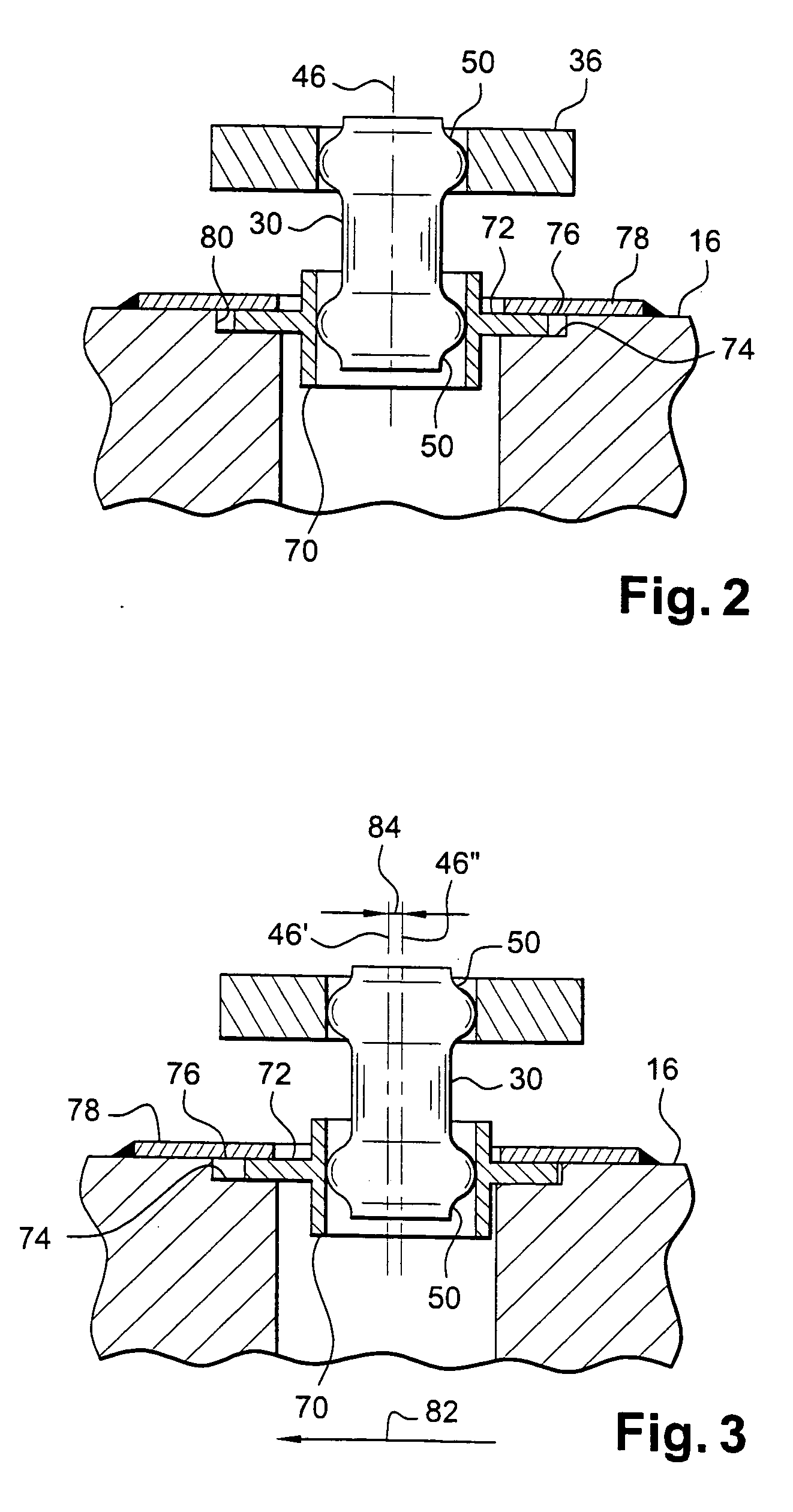
[0011] The device of the invention makes it possible to absorb offsets and changes in alignment between the orifices in the casing and in the nozzle that result from the turbomachine operating, while nevertheless ensuring continuity of the fluid link between the above-mentioned enclosure and the stator nozzle, and while avoiding wear at the ends of the tubes, and avoiding applying stresses to said tubes.
[0013] The tubes therefore do not contribute to compensating the relative displacements between the casing and the nozzle, thereby limiting the extent to which they suffer wear by friction and thus increasing their lifetime.
[0015] Advantageously, the rings of the device of the invention can be associated with prior art tubes having enlarged ends, which is very inexpensive.

Problems solved by technology

While the turbomachine is in operation, the casing, and above all the stator nozzles, expand thermally and are subjected to high levels of vibration, thereby generating relative displacements and changes in alignment between the orifices in the casing and those in the nozzles.
Nevertheless, that solution is not satisfactory insofar as mounting the ends of the tubes as tight-fits limits the extent to which they can pivot and leads to zones that present high degrees of wear due to friction against the inside surfaces of the orifices in the casing and in the nozzles, which can lead to leaks at said ends, and even to the link tubes being lost or failing.
Nevertheless, that solution is unsatisfactory since it does not make it possible to compensate relative displacements in rotation between the casing and the nozzle without leading to high degrees of wear in the link tube.

Method used


Image

  • Link device between an enclosure for passing cooling air and a stator nozzle in a turbomachine
  • Link device between an enclosure for passing cooling air and a stator nozzle in a turbomachine
  • Link device between an enclosure for passing cooling air and a stator nozzle in a turbomachine

Examples


Embodiment Construction

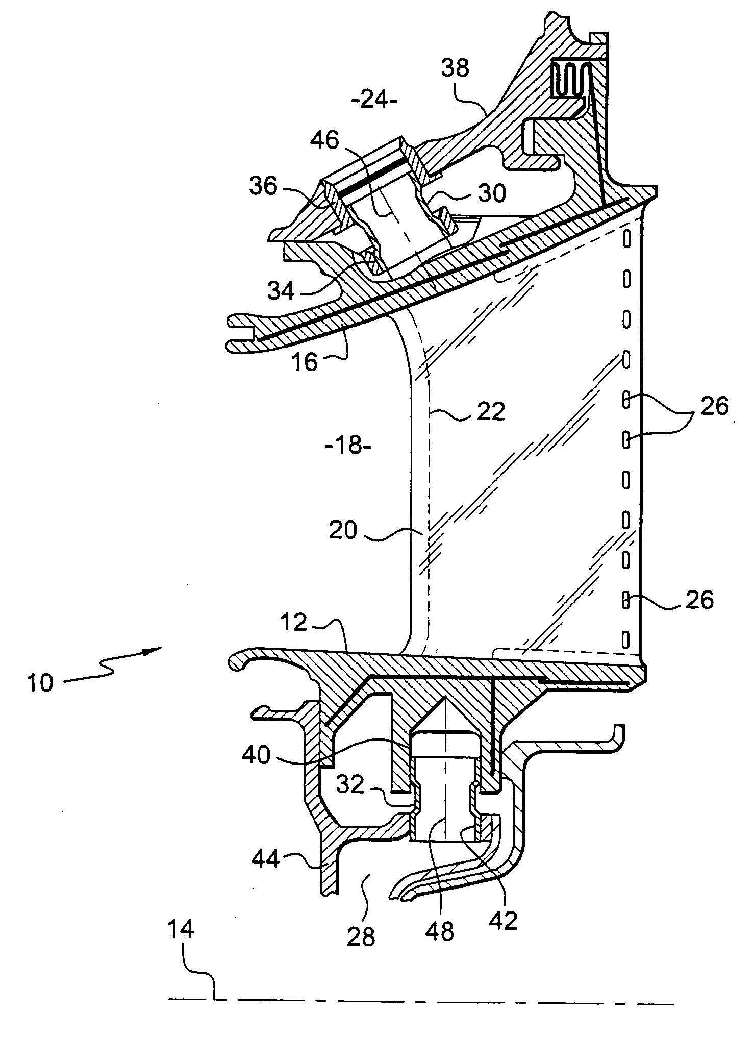
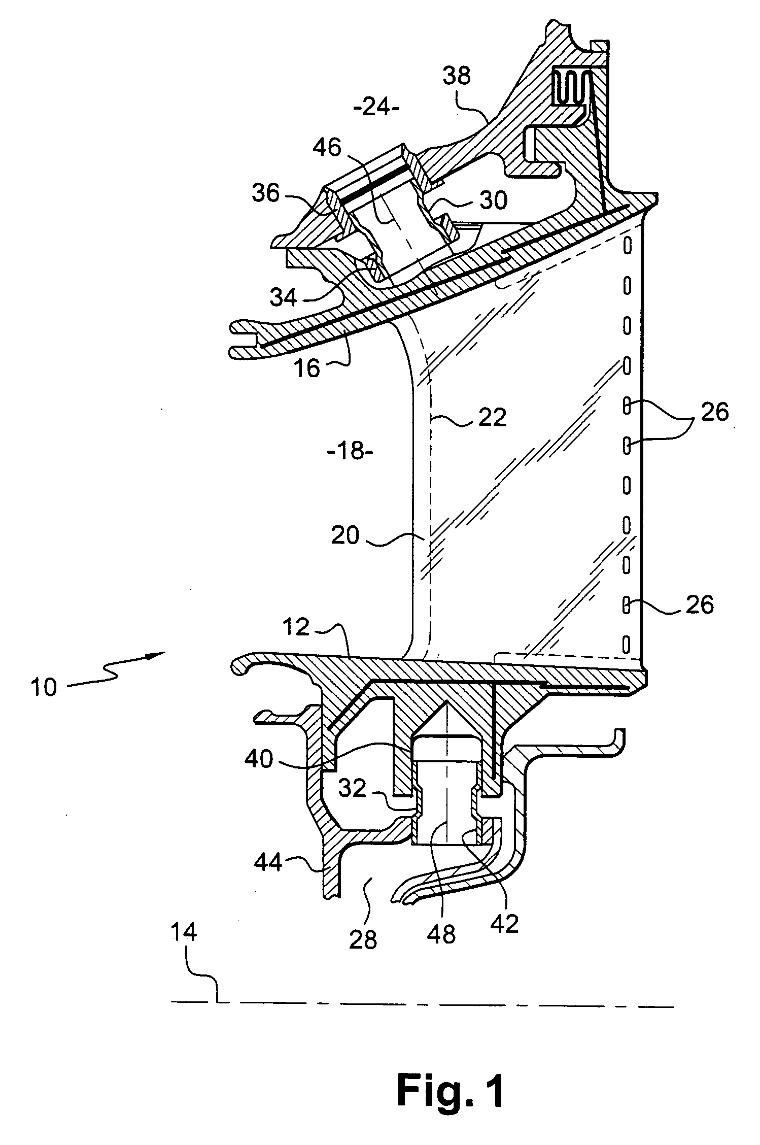
[0021]FIG. 1 is a fragmentary diagrammatic half-view in axial section of a stator nozzle 10 in a turbomachine, having a radially inner annular wall 12 of axis 14 and a radially outer frustoconical wall 16 of axis 14, sloping towards the axis 14 at its upstream end, the annular walls defining between them an annular gas flow passage 18 for gas coming from a combustion chamber (not shown) of the turbomachine, with vanes 20 extending radially between the annular walls.

[0022] Each vane 20 has an internal cavity 22 for circulating cooling air coming from a feed enclosure 24 located radially outside the wall 16 of the nozzle, part of the air being diffused into the annular passage 18 via slots 26 in the vanes 20, and part being exhausted into an enclosure 28 located radially inside the wall 12 of the nozzle.

[0023] The cavities 22 in the vanes are connected to the outer and inner enclosures 24 and 28 by link devices comprising respective metal tubes 30 and 32.

[0024] The tubes 30 for pas...


PUM


Abstract

A link device between an enclosure for passing cooling air and a stator nozzle in a turbomachine, the device comprising metal tubes having their ends mounted in leaktight manner in orifices in a casing and in orifices in the stator nozzle, one end of each tube being engaged in a ring having an outer collar movable in sliding between two surfaces carried by the nozzle, the guide surface situated beside the casing being held stationary relative to the nozzle, while the other guide surface is movable axially relative to the nozzle and is associated with return means urging it towards the casing.

Description

[0001] The present invention relates to a link device between an enclosure for passing cooling air, such as a source of cooling air or a plenum enclosure, and a stator nozzle in a turbomachine, such as an airplane turbojet or turboprop. BACKGROUND OF THE INVENTION [0002] In a turbomachine, the stator nozzles that are exposed to high temperatures, in particular those downstream from the combustion chamber, include internal cavities for passing a flow of cooling air coming from a radially outer enclosure, part of which air can be diffused into the passage for passing the flow of combustion gas via holes formed in the vanes, and part of it can be exhausted into a radially inner enclosure. [0003] Link means are provided between these enclosures and the stator nozzles to allow cooling air to pass, while minimizing losses and leaks at the interfaces, the link means comprising metal tubes having their ends mounted in leaktight manner in orifices in a casing and in orifices in the stator no...

Claims


Application Information

Patent Timeline
IPC IPC(8): F01D9/00
CPCF01D5/08F01D9/041F01D9/065F01D11/005F16L41/02Y02T50/676Y02T50/60
Inventor DERVAUX, ALEXANDREBERMOND, SABINE
Owner SN DETUDE & DE CONSTR DE MOTEURS DAVIATION S N E C M A
Learn More