
Device for lubricating a component in a turbomachine

a technology for lubricating components and turbomachines, which is applied in the direction of machines/engines, mechanical apparatus, liquid fuel engines, etc., can solve the problems of hot points, oil leakage between the radial end face of the support part and the upstream end of the annular enclosure of the cover, and is not effective in sealing the lubrication chamber of the bearing. , to achieve the effect of simple, effective and inexpensiv

Inactive Publication Date: 2007-08-07
SN DETUDE & DE CONSTR DE MOTEURS DAVIATION S N E C M A
View PDF5 Cites 3 Cited by
  • Summary
  • Abstract
  • Description
  • Claims
  • Application Information

AI Technical Summary

Benefits of technology

[0008]A particular object of the invention is to provide a solution to this problem that is simple, inexpensive, and effective.
[0009]The invention provides a device of the above-specified type for lubricating a component of a turbomachine, in which the annular gasket can be used without risk of the gasket deteriorating and without risk of oil leaking out from the lubrication chamber.

Problems solved by technology

This gasket is generally an elastomer gasket of the Viton® type with limited ability to withstand temperatures above 200° C. It is therefore not effective in sealing the lubrication chamber of the bearing, and, while the turbomachine is in operation, oil leaks can appear between the radial end face of the support part and the upstream end of the annular enclosure of the cover.
These oil leaks increase the oil consumption of the lubrication device, and can also lead to coke being deposited on the components of the turbomachine situated close to the leak, which deposit can form hot points and reduce lifetime.

Method used


Image

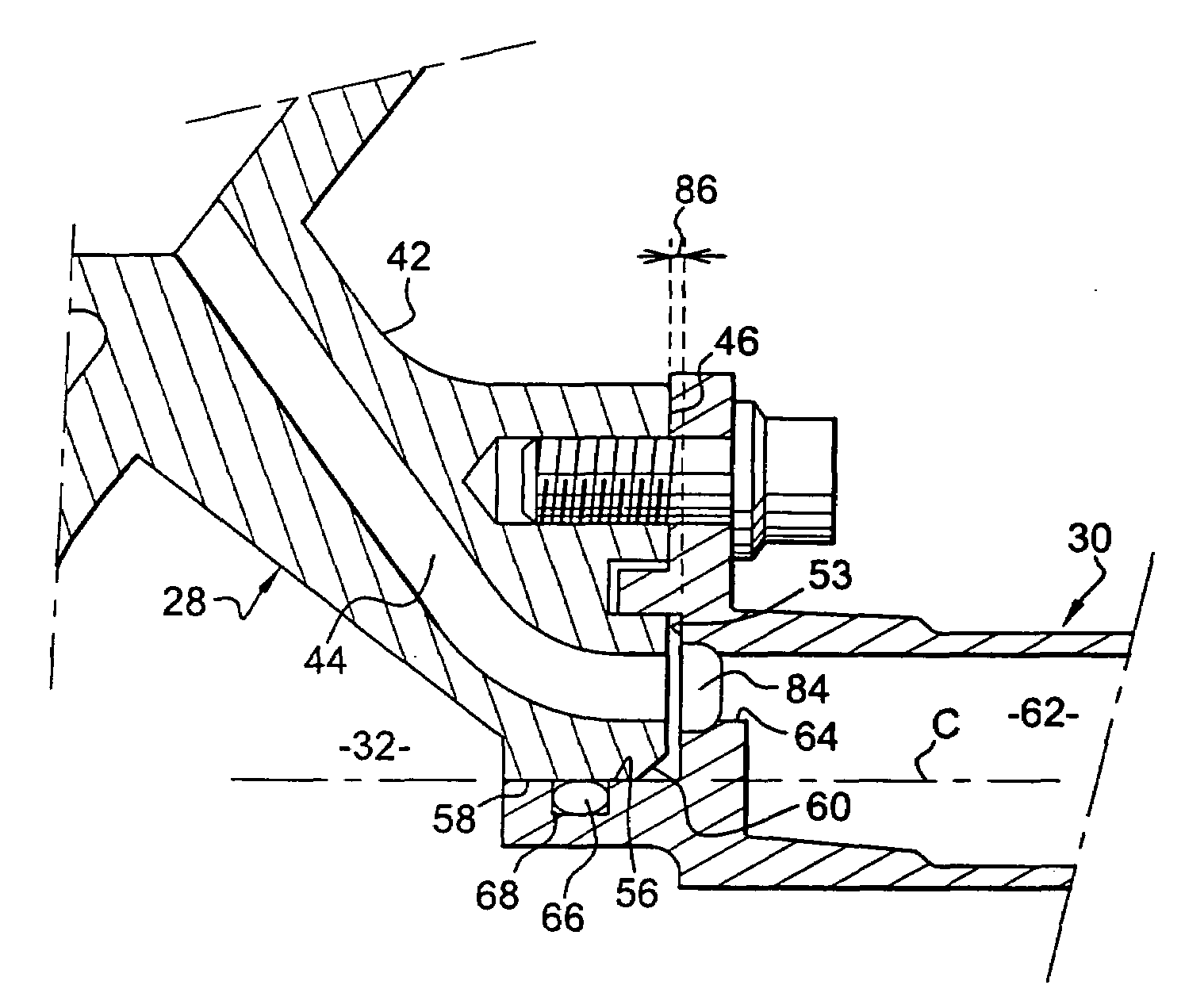
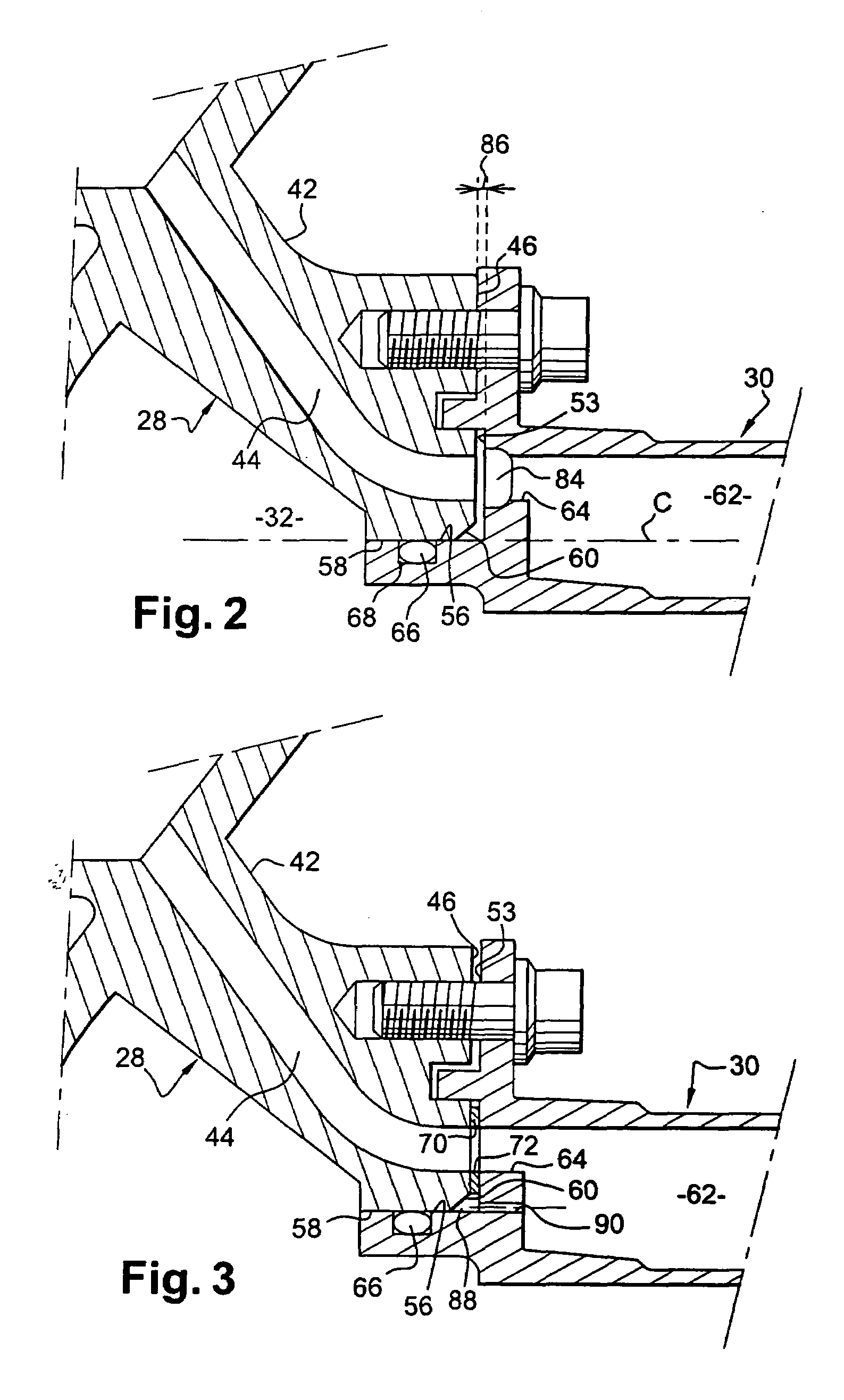
  • Device for lubricating a component in a turbomachine
  • Device for lubricating a component in a turbomachine
  • Device for lubricating a component in a turbomachine

Examples


Embodiment Construction

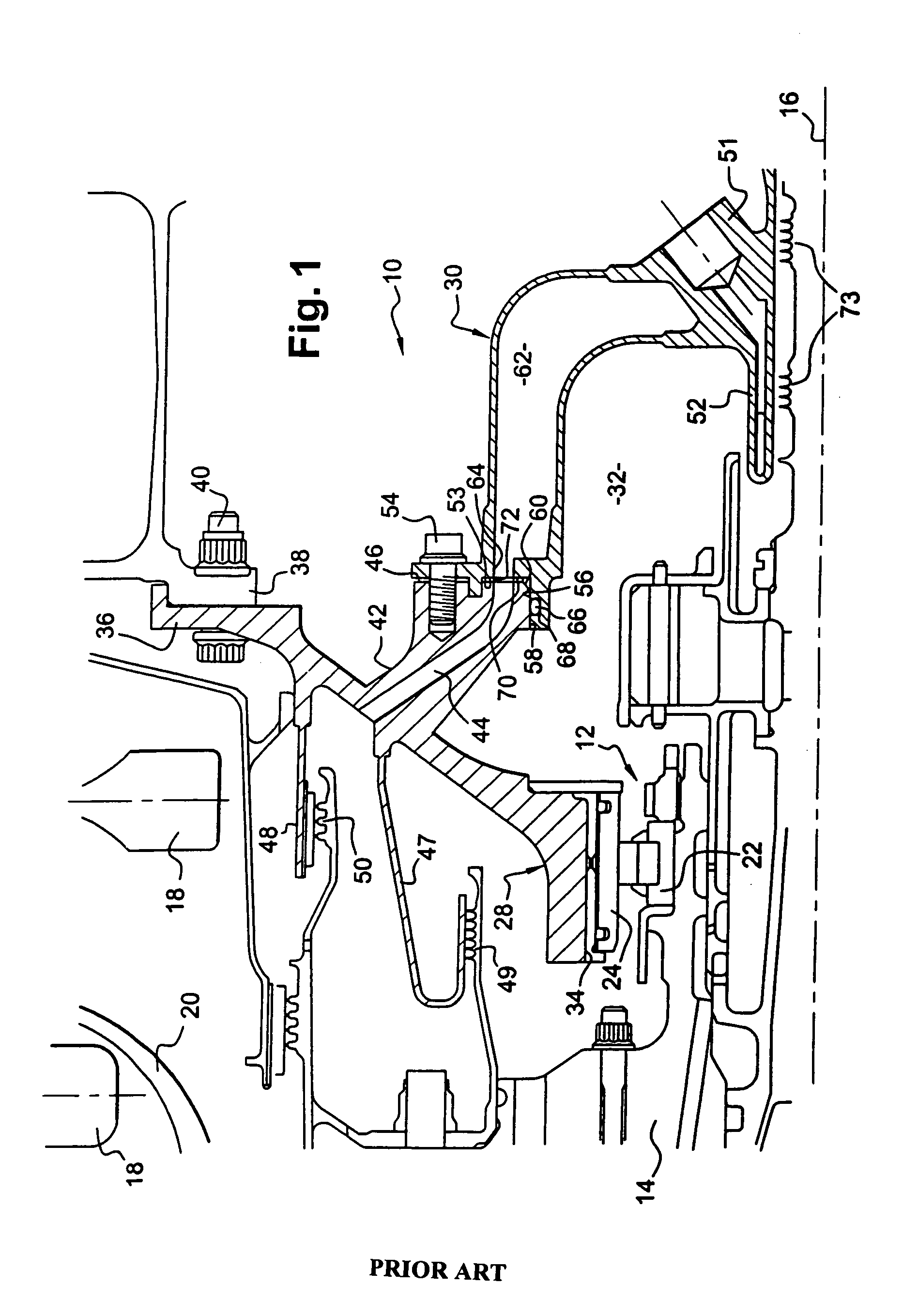
[0025]In the drawings, the left is upstream or towards the front while the right is downstream or towards the rear of the turbojet.

[0026]Reference is made initially to FIG. 1 which is a diagrammatic longitudinal half-view of a prior art device 10 for lubricating a bearing 12 of a low pressure turbine shaft 14 of a turbojet, shown in fragmentary section on a plane containing the axis 16 of rotation of the turbine.

[0027]The turbine rotor comprises turbine disks 18 shown in part that are connected to one another and that carry at their peripheries stages of moving blades (not shown), the disks 18 being separated from one another by stationary vane stages (not shown) and being connected to the turbine shaft 14 via a drive cone 20 that is shown in part.

[0028]In the example shown, the bearing 12 is a rolling bearing whose inner cap 22 is carried by the shaft 14 and whose outer cap 24 is carried by an annular part 28 provided with an annular cover 30 and defining an annular lubrication cha...


PUM


Abstract

A device for lubricating a component in a turbomachine, in particular a shaft bearing in a turbojet, the device comprising an annular support part defining a lubrication chamber around the component, an annular cover mounted in sealed manner on the part and including a lubricating oil inlet, and an annular channel for passing a flow of pressurizing and cooling air, which channel is formed between the part and the cover, and communicates with ducts in the support part and an annular enclosure formed in the cover for passing the pressurizing and cooling air.

Description

[0001]The present invention relates to a device for lubricating a component in a turbomachine, in particular a shaft bearing in a turbojet.BACKGROUND OF THE INVENTION[0002]A turbomachine comprises a gas turbine having a plurality of fixed vane stages and a plurality of moving blade stages carried by a rotor mounted on a turbine shaft. The turbine shaft is centered and guided in rotation by bearings that need to be fed continuously with oil in order to limit friction wear thereof.[0003]A known device for lubricating a turbomachine bearing comprises:[0004]an annular bearing support part mounted on the stator of the turbomachine and defining a lubrication chamber around the bearing; and[0005]an annular cover having an inlet for oil for lubricating the bearing, the annular cover being mounted in sealed manner on a radial end face of the annular support part, sealing being provided by an annular gasket mounted between the support part and the cover, and said cover including an annular en...

Claims


Application Information

Patent Timeline
Patent Type & Authority Patents(United States)
IPC IPC(8): F01D25/26
CPCF01D25/08F01D25/183F01D25/125Y02T50/675Y02T50/60
Inventor PRESTEL, SEBASTIEN JEAN-LAURENTRENON, OLIVIERSOUPIZON, JEAN-LUC
Owner SN DETUDE & DE CONSTR DE MOTEURS DAVIATION S N E C M A
Learn More