
System and method for cooling components rotatable about an axis

a cooling component and rotating technology, applied in tomography, instruments, applications, etc., can solve the problems of temperature drift, change in gantry air temperature, cooling and temperature control of electronics to directly affect the control of sensitive x-ray detectors

Active Publication Date: 2006-09-28
GENERAL ELECTRIC CO
View PDF7 Cites 28 Cited by
  • Summary
  • Abstract
  • Description
  • Claims
  • Application Information

AI Technical Summary

Problems solved by technology

Further, the electronic components and X-ray tube generate significant heat, which may cause air temperature to rise inside the gantry, thereby leading to temperature drift.
In addition, variation in a temperature of a room, where the CT system is installed, may also cause changes in the gantry air temperature.
This causes the cooling and temperature control of the electronics to directly impact the control of the sensitive X-ray detector.

Method used


Image

  • System and method for cooling components rotatable about an axis
  • System and method for cooling components rotatable about an axis
  • System and method for cooling components rotatable about an axis

Examples


Embodiment Construction

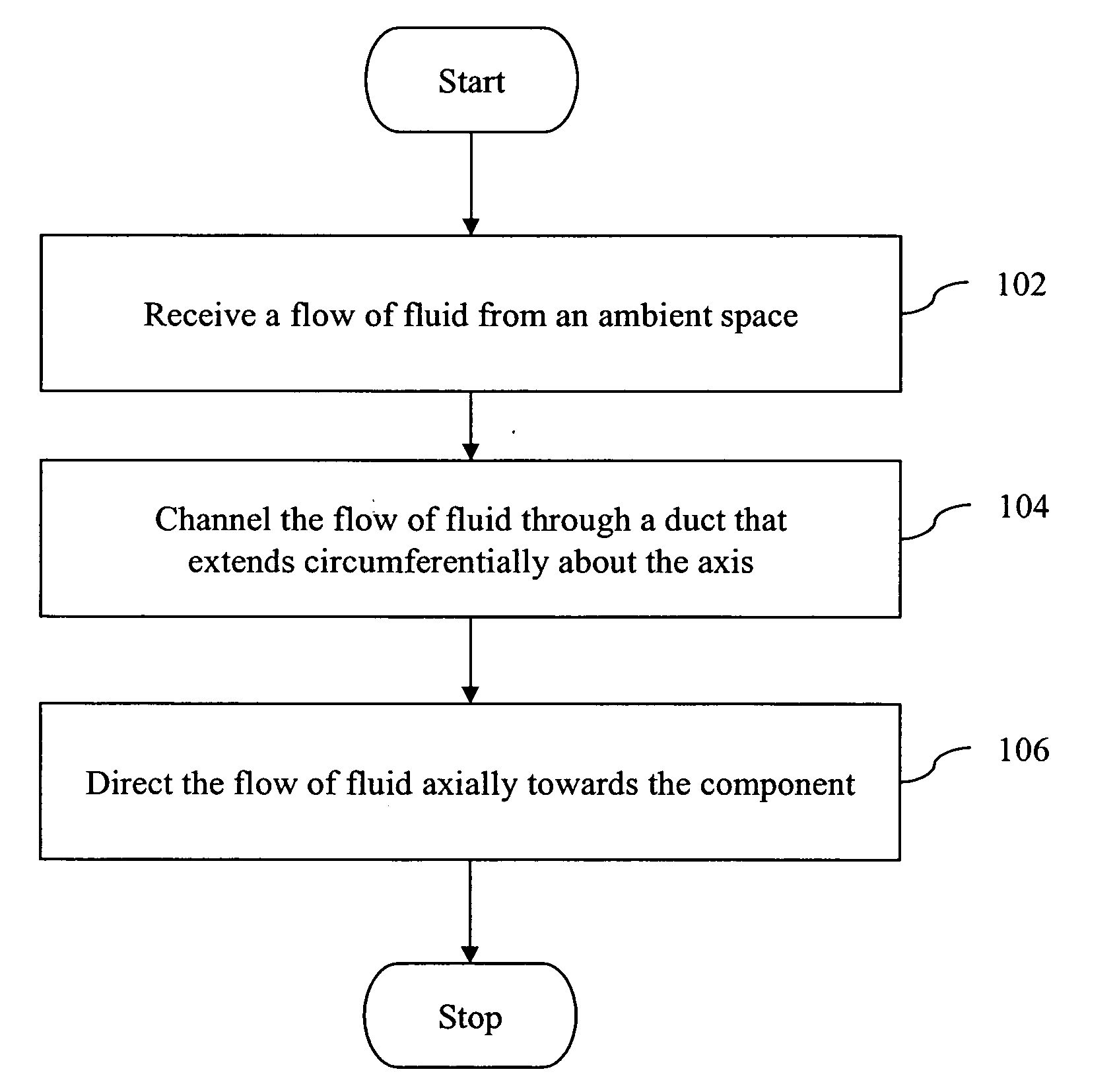
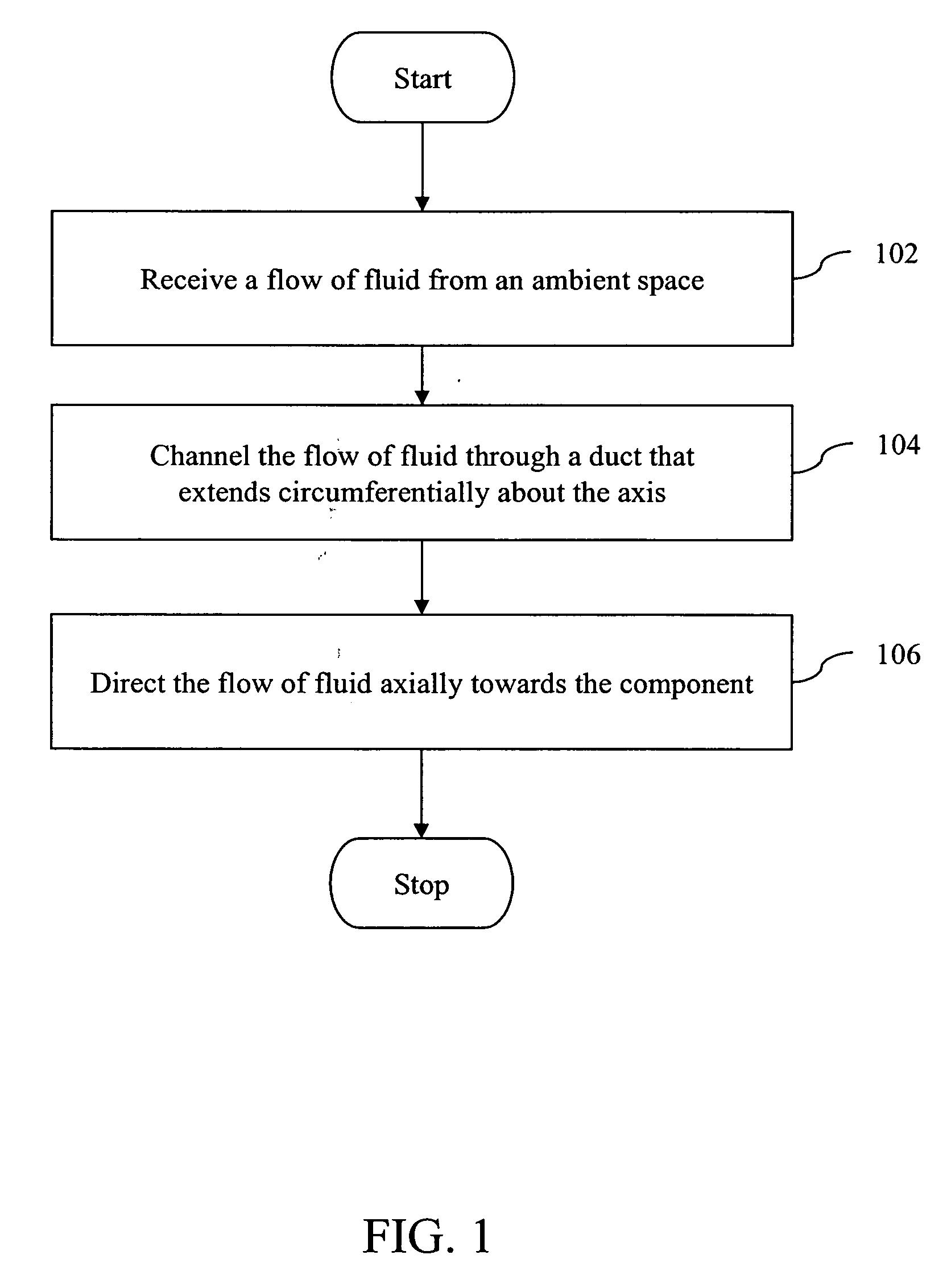
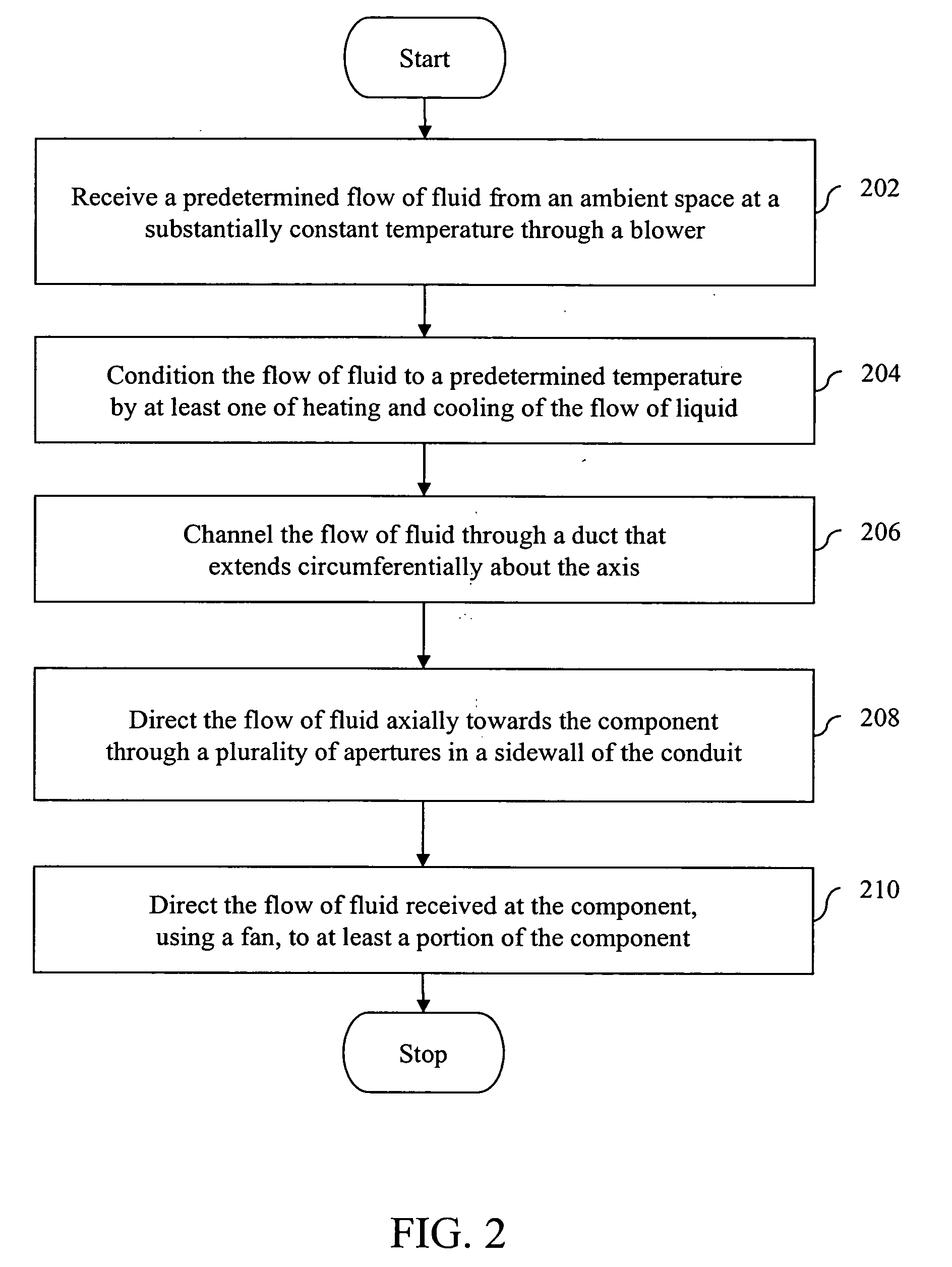
[0018] Various embodiments of the invention provide methods and systems for cooling components that are rotatable about an axis. The method of cooling the components includes receiving a flow of fluid from an ambient space, channeling the flow of fluid through a duct that extends circumferentially about the axis, and directing the flow of fluid axially towards the component. The system provided by the invention is a medical imaging device gantry. The medical imaging device gantry includes a stationary portion comprising a bore, a rotatable portion that is coupled to the stationary portion, and a component cooling system positioned at least partially within the stationary portion. The component cooling system is configured to channel a curtain of conditioned air to the electronic component.

[0019] An example of a medical imaging device may be a CT system, or a Positron Emission Tomography (PET) system.

[0020]FIG. 1 is a flowchart depicting a method performed for cooling a component t...


PUM


Abstract

Systems and methods for cooling electronic components that are rotatable about an axis are provided. The system includes a stationary portion, a rotatable portion, and a component cooling system. The stationary portion has a bore there through. The rotatable portion is rotatably coupled to the stationary portion. The rotatable portion includes an imaging detector and an associated electronic component. The component cooling system is positioned at least partially within the stationary portion and configured to channel a curtain of conditioned air to the electronic component.

Description

BACKGROUND OF THE INVENTION [0001] The invention relates generally to cooling components of a medical imaging device, and more particularly, to cooling components of a medical imaging device that are rotatable about an axis. [0002] A medical imaging device such as a Computed Tomography (CT), or a Positron Emission Tomography (PET) system, is used to generate images of body parts. The CT system includes an annular gantry that receives a patient within a gantry bore and rotates about the patient. The gantry includes an X-ray source to project a fan shaped X-ray beam extending along the plane of rotation of the gantry toward the bore. The X-ray beam passes through the patient where it is then received by a detector array. The detector array is held on the gantry opposite to the X-ray source with respect to the bore. The detector array receives the X-rays that pass through the patient's body. As a result, raw data is acquired by the detector array in response to the received X-rays. [00...

Claims


Application Information

Patent Timeline
IPC IPC(8): H05G1/60A61B6/00G01N23/00G21K1/12
CPCA61B6/037A61B6/4488
Inventor LACEY, JOSEPH JAMES
Owner GENERAL ELECTRIC CO
Learn More