
Method and tooling for forming sheet material with bend controlling displacements

a technology of displacement and forming method, applied in the direction of additive manufacturing apparatus, etc., can solve the problems of inability to punch and stamp, and inability to meet the requirements of sheet material of relatively heavy gaug

Inactive Publication Date: 2006-09-28
IND ORIGAMI INC CA US
View PDF64 Cites 21 Cited by
  • Summary
  • Abstract
  • Description
  • Claims
  • Application Information

AI Technical Summary

Benefits of technology

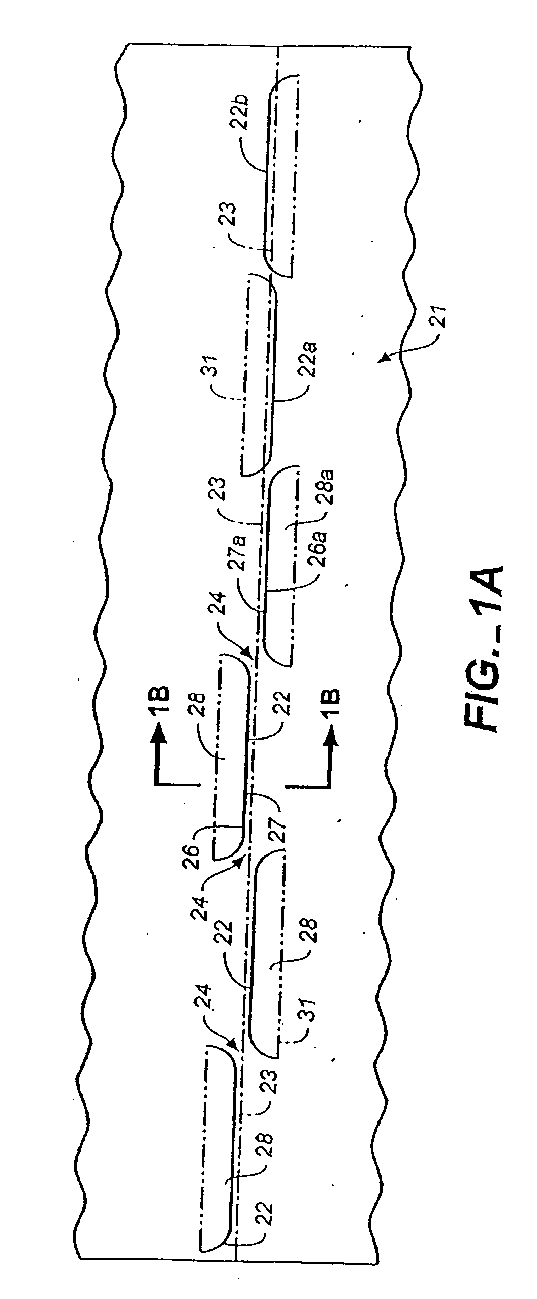
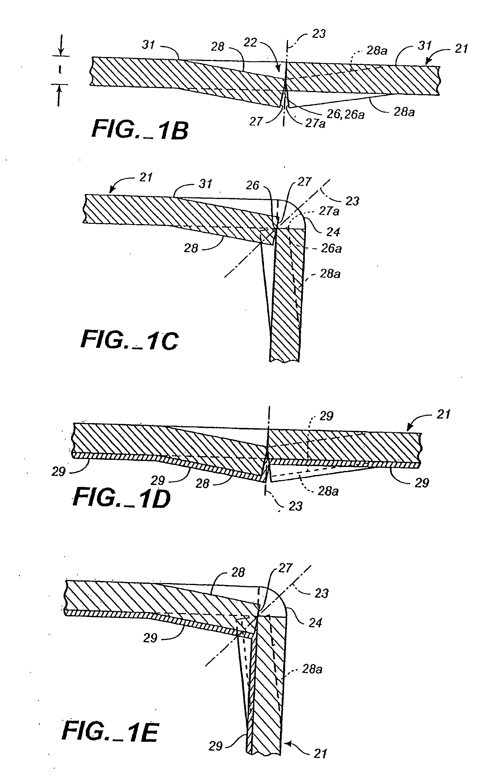
[0015] A sheet of material suitable for bending along a bend line is also provided which comprises, briefly, a sheet having at least one displacement in the thickness direction of the sheet, with a portion of the displacement closest to the bend line providing an edge and an opposing face configured to produce edge-to-face engagement of the sheet of material on opposed sides of the portion of the periphery during bending. Most preferably a plurality of displacements are positioned along the bend line on alternating sides of the bend line. A continuous layer of coating material can be placed on the sheet before bending to further insure that resulting bend will be fluid-tight, corrosion resistant and attractive. The displacements in the sheet of material can extend partially through the sheet or completely through it, and the sheet can be bent in the direction of the displacements for maximum precision or in an opposed direction by relying on the oblique bending straps to control the precision. Optionally, but less desirably, the sheet may be bent in the opposite direction when the precision achievable by edge-to-face bending is not required.

Problems solved by technology

Some of these processes for fabricating bend-inducing slit geometries can be more expensive than others.
For example, laser cutting will inherently involve additional cost as compared to, for example, punching or stamping, but punching and stamping may not be particularly well suited to sheet material of relatively heavy gauge.

Method used


Image

  • Method and tooling for forming sheet material with bend controlling displacements
  • Method and tooling for forming sheet material with bend controlling displacements
  • Method and tooling for forming sheet material with bend controlling displacements

Examples


Embodiment Construction

[0082] Reference will now be made in detail to the preferred embodiments of the present invention, examples of which are illustrated in the accompanying drawings. While the invention will be described in conjunction with the preferred embodiments, it will be understood that they are not intended to limit the invention to those embodiments. On the contrary, the invention is intended to cover alternatives, modifications and equivalents, which may be included within the spirit and scope of the invention, as defined by the appended claims.

[0083] The present method and apparatus for precision bending of sheet material is based upon the slitting geometries disclosed in the above-identified prior related applications, which are incorporated herein by reference in their entireties.

[0084] As noted in connection with the prior related applications, processes for forming the slits which will control and precisely locate the bending of sheet material include such processes as punching, stampi...


PUM

PropertyMeasurementUnit
widthaaaaaaaaaa
widthaaaaaaaaaa
widthaaaaaaaaaa

Abstract

A method of preparing a sheet of material for bending along a bend line includes the step of forming at least one displacement in the thickness direction of the sheet of material, the displacement including a flat zone substantially parallel to the sheet of material with a portion of the periphery of the flat zone extending along and adjacent to the bend line, and including an angled transition zone interconnecting the flat zone with a remainder of the sheet of material. The forming step is preferably accomplished using one of a stamping process, a punching process, a roll-forming process and an embossing process. A sheet of material suitable for bending using the process also is disclosed, as are the use of coatings, shin guards and displacing the area of the sheet between bending inducing slits.

Description

RELATED APPLICATIONS [0001] This application is a Continuation-in-Part of U.S. patent Ser. No. 11 / 080,288 filed Mar. 14, 2005 and entitled SHEET MATERIAL WITH BEND CONTROLLING DISPLACEMENTS AND METHOD FOR FORMING THE SAME, which is Continuation-in-Part of U.S. patent application Ser. No. 10 / 795,077 filed Mar. 3, 2004 and entitled SHEET MATERIAL WITH BEND CONTROLLING DISPLACEMENTS AND METHOD FOR FORMING THE SAME, which is a Continuation-in-Part of U.S. patent application Ser. No. 10 / 672,766 filed Sep. 26, 2003 and entitled TECHNIQUES FOR DESIGNING AND MANUFACTURING PRECISION—FOLDED, HIGH STRENGTH, FATIGUE-RESISTANT STRUCTURES AND SHEET THEREFOR, which is a Continuation-in-Part of U.S. patent application Ser. No. 10 / 256,870 filed Sep. 26, 2002 and entitled METHOD FOR PRECISION BENDING OF SHEET MATERIALS, SLIT SHEET AND FABRICATION PROCESS, which is a Continuation-in-Part of U.S. patent application Ser. No. 09 / 640,267 filed Aug. 17, 2000 and entitled METHOD FOR PRECISION BENDING OF A S...

Claims


Application Information

Patent Timeline
Patent Type & Authority Applications(United States)
IPC IPC(8): B21D31/02
CPCB21D5/00B21D11/20B21D28/26B33Y80/00B21D28/00
Inventor DURNEY, MAX W.
Owner IND ORIGAMI INC CA US
Learn More