
Wiring connection structure for bicycle

a technology for connecting structures and bicycles, applied in cycle equipments, coupling device connections, optical signals, etc., can solve problems such as difficulty in waterproofing structures, poor insulation or falling off of wiring, and electrical wiring may be caught by obstacles to be cut or damaged, etc., to achieve convenient connection, improve waterproof properties, and low cost

Inactive Publication Date: 2006-09-21
SHIMANO INC
View PDF11 Cites 11 Cited by
  • Summary
  • Abstract
  • Description
  • Claims
  • Application Information

AI Technical Summary

Benefits of technology

[0005] An object of the present invention is to provide a wiring connection structure for electrically connecting two electrical components that is easily made waterproof and can prevent poor insulation or falling off of a wiring.
[0006] Another object of the present invention is to provide a wiring connection structure for electrically connecting two electrical components that facilitates insertion of a wiring into a frame.

Problems solved by technology

In the conventional wiring connection structure, the electrical wiring is connected to the connection terminal mount provided in the electrical component, and thus it is difficult to make the structure waterproof.
Thus, in the conventional wiring connection structure, the terminal mount may be exposed to the outside to cause poor insulation or falling off of the wiring resulting from corrosion by moisture.
Also, in the conventional wiring connection structure, the electrical wiring is placed in the exposed manner along the frame, and thus the electrical wiring may be caught by an obstacle to be cut or damaged.
However, it is difficult to insert the electrical wiring connected to the terminal mount outside the frame into the frame.

Method used


Image

  • Wiring connection structure for bicycle
  • Wiring connection structure for bicycle
  • Wiring connection structure for bicycle

Examples


Embodiment Construction

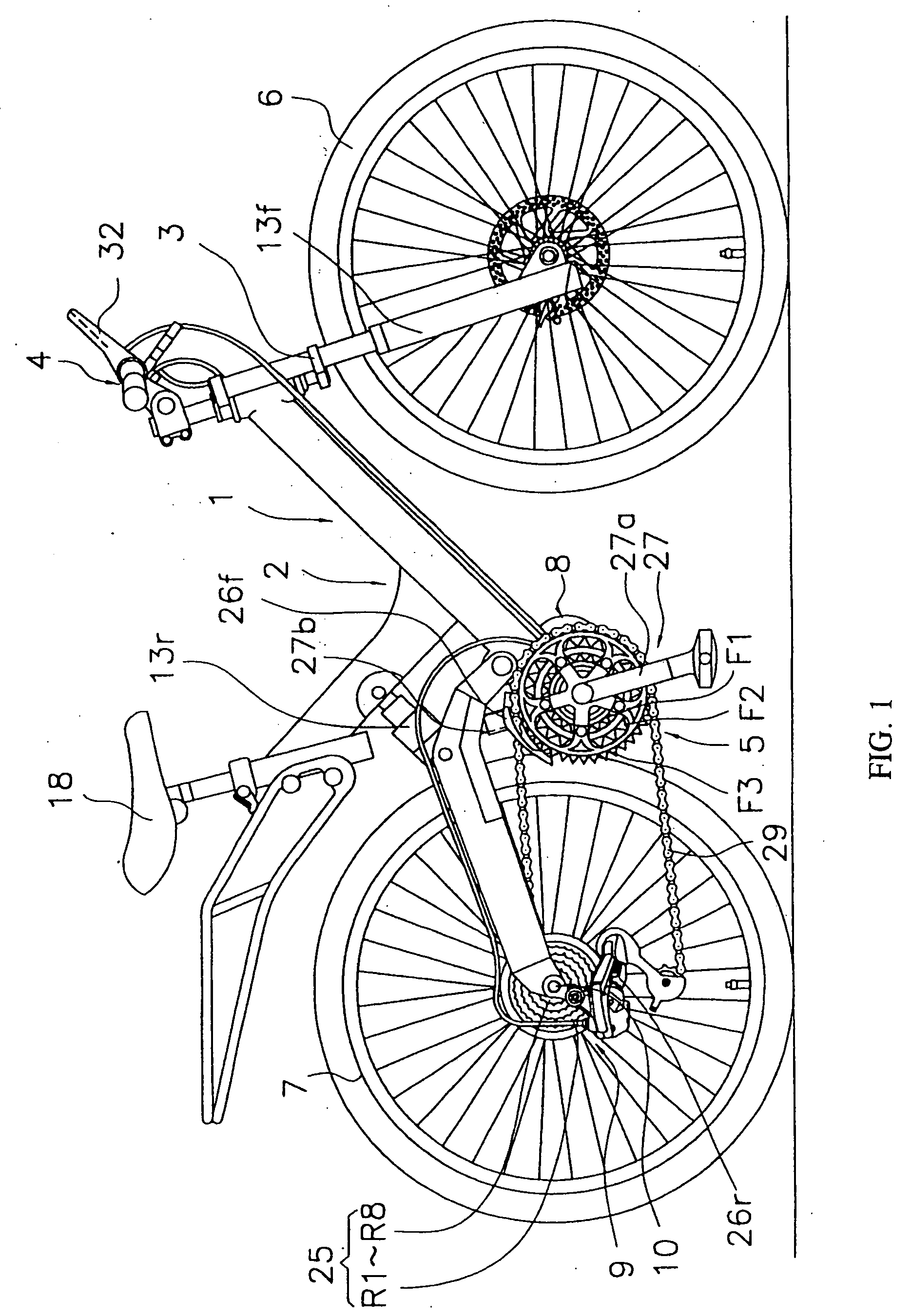
[0034] In FIG. 1, a bicycle adopting an embodiment of the present invention is a mountain bike with front and rear suspensions, and includes a frame 1 having a frame body 2 with a rear suspension 13r, a front fork 3 with a front suspension 13f, and a handle portion 4 (an example of a handle), a drive portion 5 including front and rear shift devices 8 and 9, a front wheel 6 mounted to the front fork 3, a rear wheel 7 to which a hub dynamo 10 is mounted, and a control device 11 (FIG. 3) for controlling portions including the front and rear shift devices 8 and 9.

[0035] The frame body 2 of the frame 1 is created by welding an odd-form rectangular pipe. Portions including a saddle 18 and the drive portion 5 are mounted to the frame body 2. The front fork 3 is oscillably mounted around a tilted shaft in front of the frame body 2.

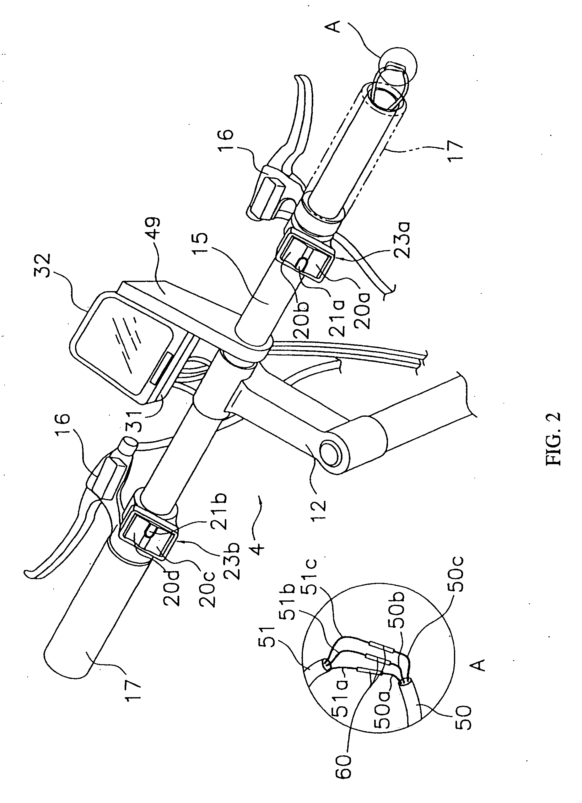
[0036] As shown in FIG. 2, the handle portion 4 includes a handle stem 12 secured to an upper portion of the front fork 3, and a handlebar 15 secured to the han...


PUM


Abstract

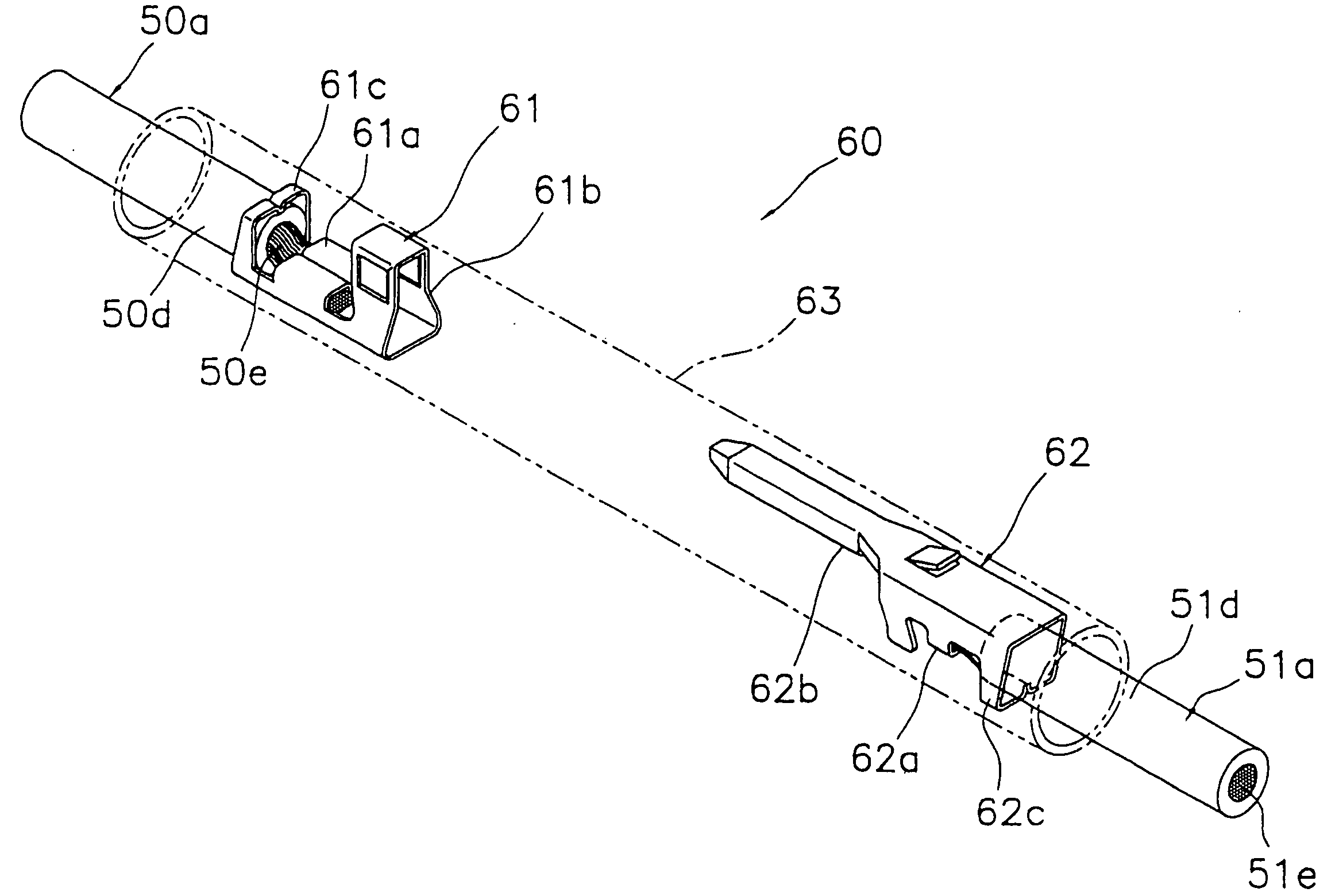
There is provided a wiring connection structure for electrically connecting two electrical components that is easily made waterproof and can prevent poor insulation or falling off of a wiring. The wiring connection structure 60 for a bicycle is a structure for electrically connecting a first electrical wiring 50 connected to a switch unit 23a mounted to a handlebar 15 and a second electrical wiring 51 connected to a second control unit 31, and includes a first connection terminal 61, a second connection terminal 62, and a tubular cover member 63. The first connection terminal 61 is a terminal electrically connectable to the first electrical wiring 50. The second connection terminal 62 is a terminal electrically connectable to the second electrical wiring 51 and the first connection terminal 61. The cover member 63 is a heat-shrinkable synthetic resin member covering at least both the connection terminals 61 and 62.

Description

FIELD OF THE INVENTION [0001] The present invention relates to a wiring connection structure, and more particularly to a wiring connection structure for a bicycle for electrically connecting a first electrical wiring connected to a first electrical component mounted to a frame of the bicycle including a handle and a second electrical wiring mounted to a second electrical component. BACKGROUND OF THE INVENTION [0002] Recent bicycles have incorporated many electrical components besides a lamp. For example, electrical components such as an electric drive force assist device for assisting a drive force from pedals or an electric shift device for electrically or pneumatically performing a shift operation have been widely used. Many electrical components for controlling or operating these electrical components have been also used. In a conventional wiring connection structure for connecting these electrical components, terminals attached to electric wirings are connected to a connection t...

Claims


Application Information

Patent Timeline
Patent Type & Authority Applications(United States)
IPC IPC(8): H01R13/44B62J11/19B62J99/00
CPCB62J6/18B62K23/02B62M25/08H01R4/185H01R13/113H02G15/1806B62J11/19Y10S439/932
Inventor ONOGI, TAKUMIMIYOSHI, HIROYUKI
Owner SHIMANO INC
Learn More