
Method and apparatus for multiple labeling detection and evaluation of a plurality of particles

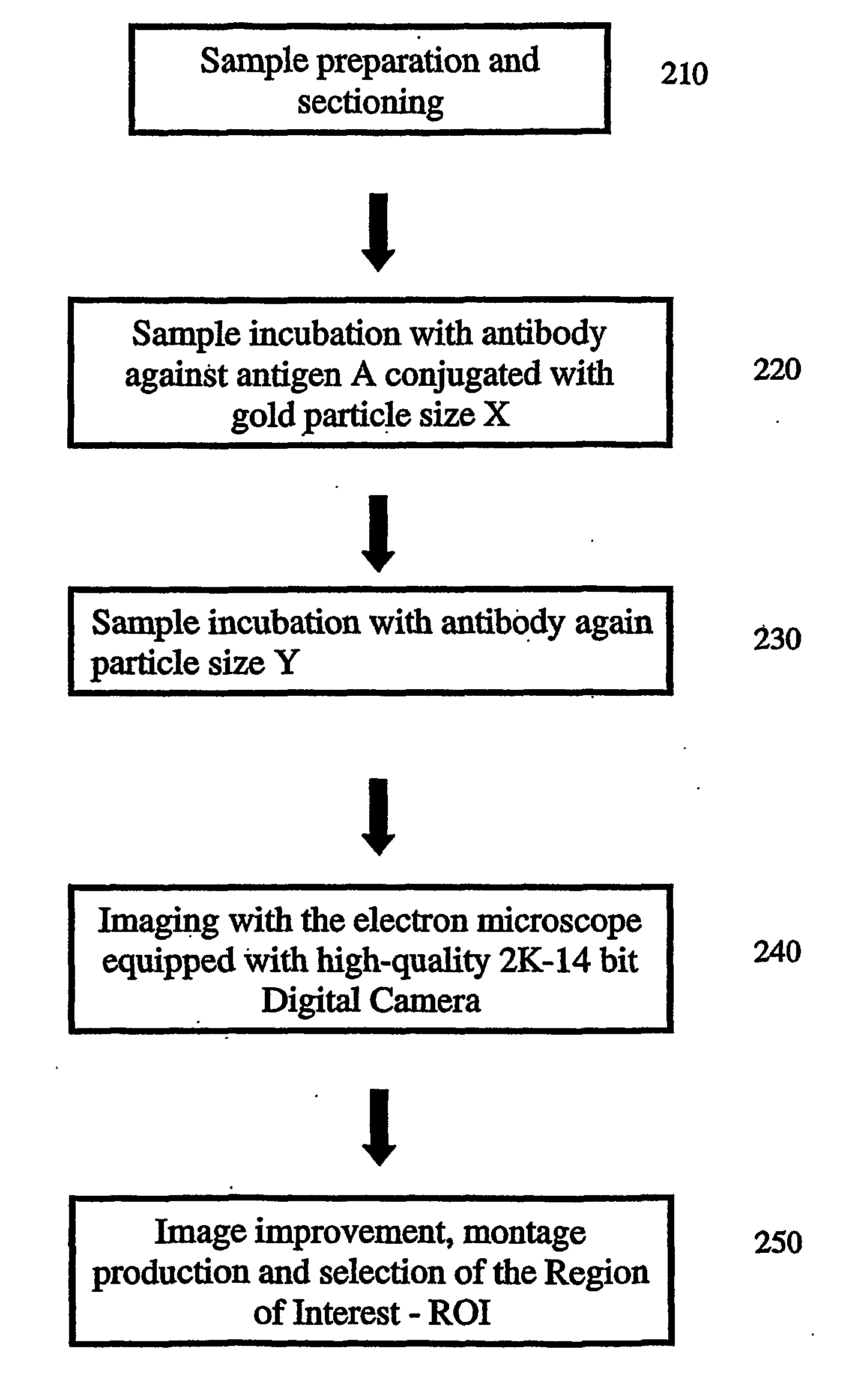
a technology of multiple labeling and particle detection, applied in the field of multiple labeling detection and evaluation of a plurality of particles, can solve the problems of not being able to the need to use electron-dense particles and observe a gray scale image in the em, etc., and achieve the effect of fast and reliabl

Inactive Publication Date: 2006-09-21
DEUTES KREBSFORSCHUNGSZENT STIFTUNG DES OFFENTLICHEN RECHTS
View PDF4 Cites 17 Cited by
  • Summary
  • Abstract
  • Description
  • Claims
  • Application Information

AI Technical Summary

Benefits of technology

[0008] It is therefore an object of the present invention to provide researchers with an apparatus and method for the fast and reliable particle detection, counting and pseudo-color overlay.

Problems solved by technology

Unfortunately, the maximum resolution of the light microscope is not sufficient to permit the detailed identification of the sites where the antibody-antigen complex is located.
However, electron microscopes are incapable of presenting color images, as they use electrons and not photons.
The fact that one needs to use electron-dense particles and observe a gray scale image in the EM can, however, become a problem, because the contrast of the gold particles is very close to that of the background structures.
In other words, it becomes very difficult to identify the gold particles against a background that sometimes presents, for our eyes, almost the same gray values.
This problem is even more complicated, when one wants to observe multiple labeling.
This is not so easy to do in electron microscopy images.
As one of the aims of the use of markers is to comparatively evaluate the number and positions of such elements in a multiple labeling experiment, the false identification or the lack of identification of particles will lead to completely wrong conclusions.
A further complication is the necessity to use a higher magnification, in order to view the very small particles for example 3, 6, 10 nm in diameter, restricting the microscope field of view to very small regions of the sample.
The prior art tools developed failed probably because they were not reliable and were incapable of multiple localization.

Method used


Image

  • Method and apparatus for multiple labeling detection and evaluation of a plurality of particles
  • Method and apparatus for multiple labeling detection and evaluation of a plurality of particles
  • Method and apparatus for multiple labeling detection and evaluation of a plurality of particles

Examples


example

[0048] For the sake of clarity the invention was described herein using a single sample image. The following FIG. 5.1 to 5.6 display an actual example of the invention in which the image montage on the computer screen is constructed.

[0049]FIG. 5.1 shows the invention having three options. Processing the image from an image store or gallery (labeled G), acquiring the image from the microscope (L) or first creating a montage (M) of several images and then proceeding with the analysis.

[0050]FIG. 5.2 shows the first step within the montage option, the acquisition and alignment of several high resolution (2048 square pixel size) and high dynamic range (14 bit) images.

[0051] In FIG. 5.3, after the automatic conclusion of the montage, the method allows the operator to define one region of interest (ROI—defined by a frame). In this example the whole image is selected.

[0052] In FIG. 5.4 the contrast window is established. The thin line in the contrast window should only reach the beginni...


PUM


Abstract

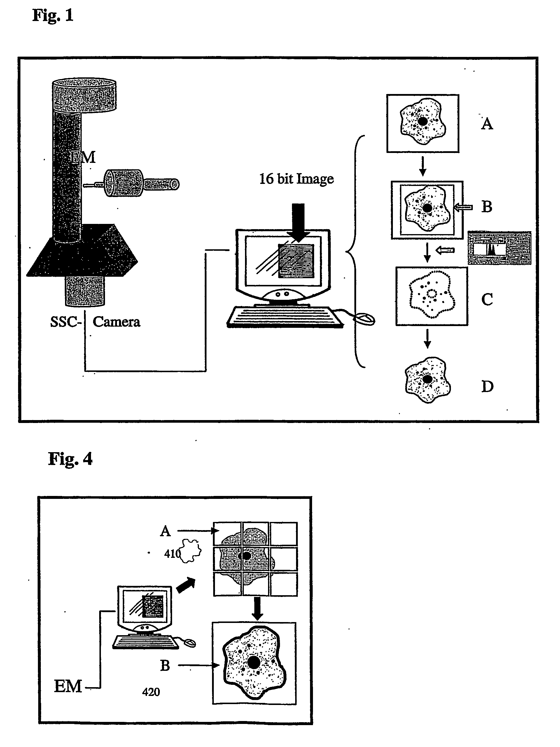
The invention relates to a transmission electron microscope equipped with a 2k−2k pixel area Slow Scan Cooled Charge Coupled Device Camera connected to an image processing software for generating an image of a sample. A segmentation of gold particles in the sample is achieved by the separation from specimen structure and background noise. An identification and classification of particle types is carried out according to the shape and size of the detected particles or particle pairs and finally, the gold particle distribution is visualized by the generation of false color overlay images as well as the indication of the numbers in the image.

Description

FIELD OF THE INVENTION [0001] The invention relates to an apparatus and method which allows the user of a microscope to automatically detect and quantify particle distributions in biological and medical microscopic specimens. INTRODUCTION TO THE INVENTION [0002] In order to visualize and identify the location of specific antibody-antigen complexes, researchers use known methods. [0003] When working with a light microscope, it is possible to associate the antibody with fluorescent markers that, with correct illumination, reveal the position of the desired complex. Unfortunately, the maximum resolution of the light microscope is not sufficient to permit the detailed identification of the sites where the antibody-antigen complex is located. [0004] In order to have more information, researchers need to use an electron microscope (EM) which is capable of revealing image details up to a few nanometers (10−9 m) in size. However, electron microscopes are incapable of presenting color images...

Claims


Application Information

Patent Timeline
IPC IPC(8): G06K9/00C12M1/34G01N23/04G01N15/14G01N33/543G02B
CPCG01N15/1475G01N33/54333G01N2015/1472G06K9/0014H01J2237/225G06V20/695G01N15/1433
Inventor TRENDELENBURG, MICHAELSPRING, HERBERTMONTEIRO-LEAL, LUIZ HENRIQUECAMPANATI-ARAUJO, LORAINETROESTER, HELMUT
Owner DEUTES KREBSFORSCHUNGSZENT STIFTUNG DES OFFENTLICHEN RECHTS
Learn More