Cascaded pump delivery for remotely pumped erbium-doped fiber amplifiers

a fiber amplifier and fiber technology, applied in the field of optical fiber telecommunication spans, can solve the problems of adding to the complexity and cost of the pump fiber, significant cost implications, etc., and achieve the effects of reducing energy consumption, and increasing the amount of pump power

Active Publication Date: 2006-09-21
MPB COMM
View PDF11 Cites 37 Cited by
  • Summary
  • Abstract
  • Description
  • Claims
  • Application Information

AI Technical Summary

Benefits of technology

[0007] In a broad aspect, the invention provides a scheme for increasing the amount of pump power that can be delivered to a remote optically pumped amplifier in an optical fiber communication system or, conversely, increasing the distance along the transmission span over which a given amount of pump power can be delivered. According to this scheme, high-order Raman amplification is used to provide amplification in the transmission span itself, or in a dedicated pump fiber, for the relatively low power at the 1480-nm ROPA pump wavelength launched from the receiving or transmitting terminal, for a remote preamplifier or post amplifier, respectively. This pumping scheme can, in a cost-effective manner, significantly improve the pump power delivery compared to prior-art pump delivery schemes.
[0010] In another exemplary embodiment, which is a variant of the foregoing example, the seed source at 1357 nm is replaced by reflection means (e.g. a gold reflector or a fiber Bragg grating with a peak reflectivity at 1357 nm). Spontaneous Raman scattering of the high-power primary pump at 1276 nm produces radiation in the 1357-nm region traveling in both directions in the fiber. As it travels in the fiber, this 1357-nm radiation is amplified due to the Raman gain at 1357 nm produced by the 1276-nm pump. In addition, some of the outgoing 1357-nm radiation undergoes Rayleigh scattering and heads back toward the pump and seed launch terminal, being further amplified as it goes. The 1357-nm reflector sends the incoming amplified spontaneous Raman scattered radiation back into the fiber, where it performs the same role as the 1357-nm seed source in the foregoing example. In an extension of this exemplary embodiment, the 1426-nm seed source is also replaced by a reflector, thereby further reducing the number of active seed sources (e.g. laser diodes) required and further reducing costs.
[0013] According to another aspect of the present invention, there is provided a system for increasing the amount of pump power that can be delivered along the transmission fiber to a remote optically pumped preamplifier and at the same time providing a broader, flatter distributed Raman gain profile for the incoming signals as they propagate from the ROPA to the receiving terminal, and which comprises: a primary pump source at wavelength λ0, shorter than the ROPA pump wavelength λp; means to provide substantially lower energy at two or more seed wavelengths λs1 . . . λsn, where n≧2 and λ0<λsn≦λp, and where the ensemble of seed sources contains at least one at the ROPA pump wavelength λp; and coupling means at the receiving terminal to input energy from the primary pump source and energy at the seed wavelengths into the segment of the transmission fiber between the ROPA and the receiving terminal; and wherein the primary pump wavelength λ0 is less than the wavelength λp by an amount corresponding to n Raman shifts in the delivery fiber and where the ensemble of seed wavelengths contains one in the vicinity of each intermediate wavelength λl, where l=n−1, n−2 . . . 1, and denotes the number of Raman shifts in the delivery fiber between the wavelength λl and the ROPA pump wavelength λp; and wherein the seed wavelength λsn in the vicinity of λl=1 is in the 1420-nm region.
[0014] According to a further broad aspect of the present invention, there is provided a method for increasing the amount of pump power that can be delivered to a remote optically pumped amplifier in an optical fiber communication system or, conversely, increasing the distance along the transmission span over which a given amount of pump power can be delivered, the method comprising the steps of: providing a primary pump source at wavelength λ0, shorter than the ROPA pump wavelength λp; providing substantially lower energy at two or more seed wavelengths λs1 . . . λsn, where n≧2 and λ0<λsn≦λp, and where the ensemble of seed sources contains at least one at the ROPA pump wavelength λp; and propagating the energy at the primary pump and seed wavelengths in the pump delivery fiber which may be either the transmission fiber itself or a dedicated pump fiber; and wherein the primary pump wavelength λ0 is less than the wavelength λp by an amount corresponding to n Raman shifts in the delivery fiber and where the ensemble of seed wavelengths contains one in the vicinity of each intermediate wavelength λl, where l=n−1, n−2 . . . 1, and denotes the number of Raman shifts in the delivery fiber between the wavelength λl and the ROPA pump wavelength λp.
[0015] According to another aspect of the present invention, there is provided a method for increasing the amount of pump power that can be delivered along the transmission fiber to a remote optically pumped preamplifier and at the same time providing a broader, flatter distributed Raman gain profile for the incoming signals as they propagate from the ROPA to the receiving terminal, the method comprising the steps of: providing a primary pump source at wavelength λ0, shorter than the ROPA pump wavelength λp; providing substantially lower energy at two or more seed wavelengths λs1 . . . λsn, where n≧2 and λ0<λsn≦λp, and where the ensemble of seed sources contains at least one at the ROPA pump wavelength λp; and propagating the energy at the primary pump and seed wavelengths toward the ROPA from the receiving terminal in the segment of the transmission fiber between said ROPA and said receiving terminal; and wherein the primary pump wavelength λ0 is less than the wavelength λp by an amount corresponding to n Raman shifts in the delivery fiber and where the ensemble of seed wavelengths contains one in the vicinity of each intermediate wavelength λl, where l=n−1, n−2 . . . 1, and denotes the number of Raman shifts in the delivery fiber between the wavelength λl and the ROPA pump wavelength λp; and wherein the seed wavelength λsn in the vicinity of λl=1 is in the 1420-nm region.

Problems solved by technology

However, as capacity and / or span length requirements increase in unrepeatered systems, distributed Raman amplification is typically implemented first and then, when even this is not sufficient, architectures with discrete EDFA amplifiers placed out in the cable and pumped remotely from the terminals are used.
Despite the improvements in delivered pump power provided by these latter developments, they require dedicated pump fibers even for a remotely-pumped preamplifier, a fact which, in and of itself, has significant cost implications.
Furthermore, the dedicated pump fiber is a hybrid PSCF / E-PSCF fiber incorporating WDM coupler filters, which adds to the complexity and cost of the pump fiber.

Method used


Image

  • Cascaded pump delivery for remotely pumped erbium-doped fiber amplifiers
  • Cascaded pump delivery for remotely pumped erbium-doped fiber amplifiers
  • Cascaded pump delivery for remotely pumped erbium-doped fiber amplifiers

Examples


example

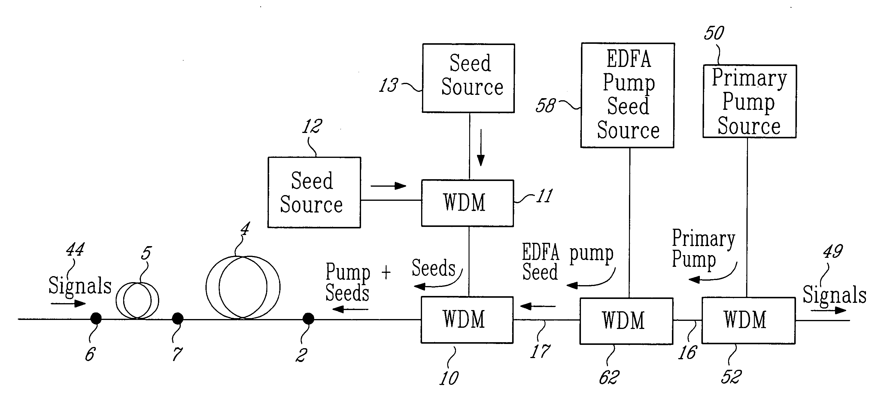
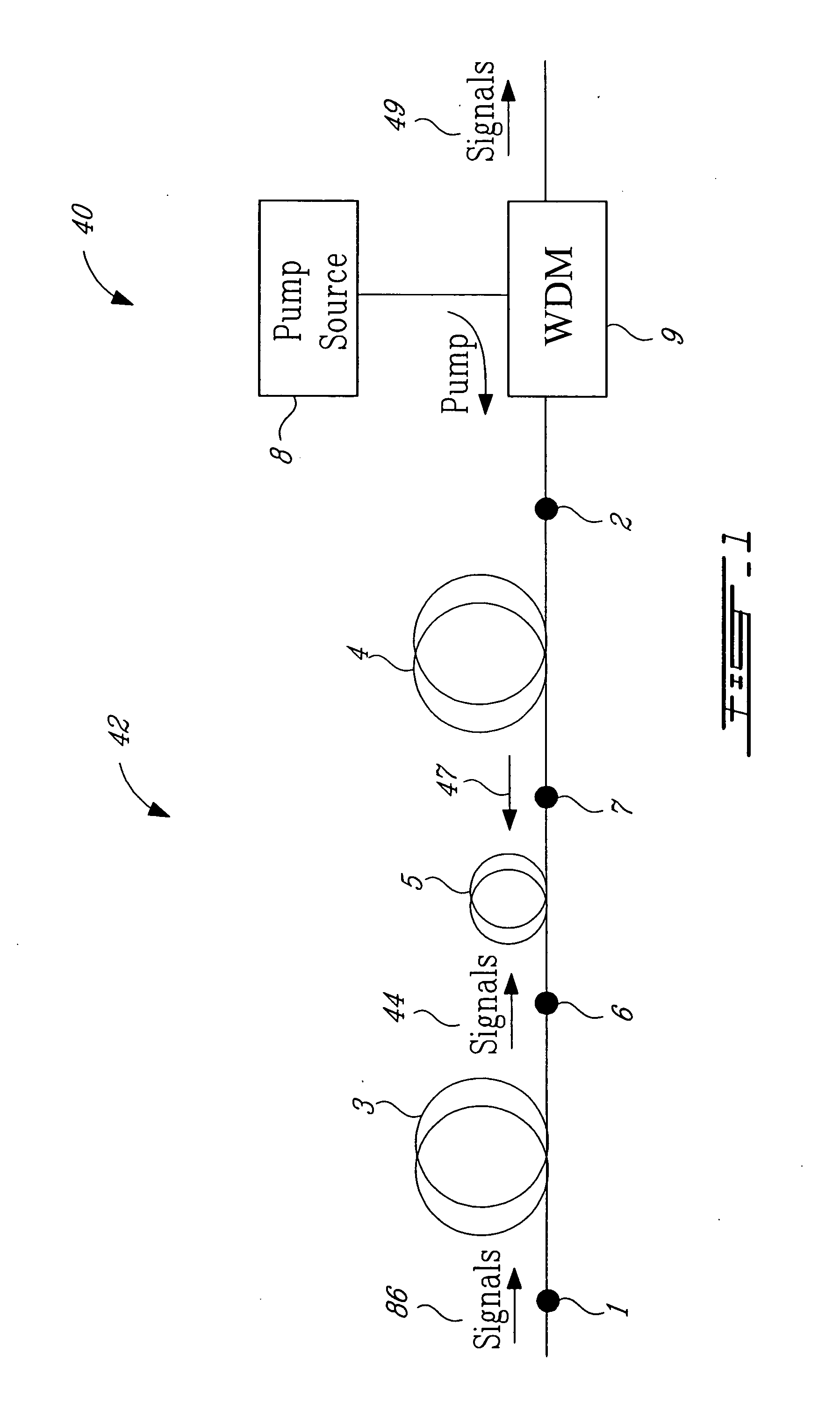
[0049] An experimental fiber-optic transmission span, incorporating a ROPA post amplifier and a ROPA preamplifier, was setup. Sumitomo Z PSCF (loss at 1550 nm=0.17 dB / km) was used throughout. The remote post amplifier was located 70 km from the transmitter terminal and was pumped along two dedicated pump fibers by two identical cascaded Raman pump modules substantially as shown in FIG. 8. The long-span fiber 88 carrying the signals from the output of the post amplifier towards the ROPA preamplifier was 314 km in length. A variable optical attenuator was inserted just before the remote preamplifier input to add an additional 3 dB of span loss. The ROPA preamplifier architecture was substantially as shown in FIG. 6 and it was pumped from the receiving terminal along the transmission fiber by a cascaded Raman pump module substantially as shown in FIG. 7. The fiber segment 4 between the receiving terminal and the ROPA preamplifier was 131 km long. The total span length was therefore 70+...


PUM


Abstract

A method for pumping remote optically-pumped fiber amplifiers (ROPAs) in fiber-optic telecommunication systems is disclosed which uses cascaded Raman amplification to increase the maximum amount of pump power that can be delivered to the ROPA. According to the prior art, high power at the ROPA pump wavelength, λp, is launched directly into the fiber and the maximum launch power is limited by the onset of pump depletion by Raman noise and oscillations due to the high Raman gain at ˜(λp+100) nm. In preferred embodiments of the present invention, a ‘primary’ pump source of wavelength shorter than λp is launched into the delivery fiber along with two or more significantly lower-power ‘seed’ sources, among which is included one at λp. The wavelength and power of the seed source(s) are chosen such that, when combined with the high-power primary source, a series, n, where n≧2, of Raman conversions within the fiber ultimately leads to the development of high power at λp. In another embodiment, one or more of the seed sources at wavelengths shorter than λp are replaced by reflecting means to return, into the fiber, backward-travelling amplified spontaneous Raman scattered light resulting from high power in the fiber at a wavelength one Raman shift below the particular seed wavelength. In either case, the high power at λp is developed over a distributed length of the fiber, reaching its maximum some distance into the fiber and exceeding the maximum power possible at that point with the prior art.

Description

FIELD OF THE INVENTION [0001] The present invention relates to amplification in optical fiber telecommunication spans and, more particularly, to remote optically-pumped erbium-doped fiber amplifiers, as are used in submarine fiber optic spans and long distance spans over land. BACKGROUND OF THE INVENTION [0002] The amplification of optical signals in fiber-optic telecommunication systems is achieved primarily through the use of discrete optical amplifiers, mainly erbium-doped fiber amplifiers (EDFAs), and through distributed Raman amplification (DRA) in which the transmission fiber itself is used as the amplifying medium. [0003] Discrete amplifiers placed as boosters or pre-amplifiers at either end of an optical cable link are sufficient for moderate span lengths and capacities. However, as capacity and / or span length requirements increase in unrepeatered systems, distributed Raman amplification is typically implemented first and then, when even this is not sufficient, architectures...

Claims


Application Information

Patent Timeline
IPC IPC(8): H01S3/00
CPCH04B10/291H04B10/2916
Inventor PAPERNYI, SERGUEILKARPOV, VLADIMIRIVANOV, VLADIMIRCLEMENTS, WALLACE
Owner MPB COMM
Why Eureka
Try Eureka