
Plasma display device and operating method of the same

Inactive Publication Date: 2006-09-21
LG ELECTRONICS INC
View PDF6 Cites 8 Cited by
  • Summary
  • Abstract
  • Description
  • Claims
  • Application Information

AI Technical Summary

Benefits of technology

[0019] An object of the present invention is to provide a plasma display device which can enhance discharge efficiency and improve an afterimage and brightness by adjusting a rising time or a falling time of a sustain pulse in driving a plasma display panel.
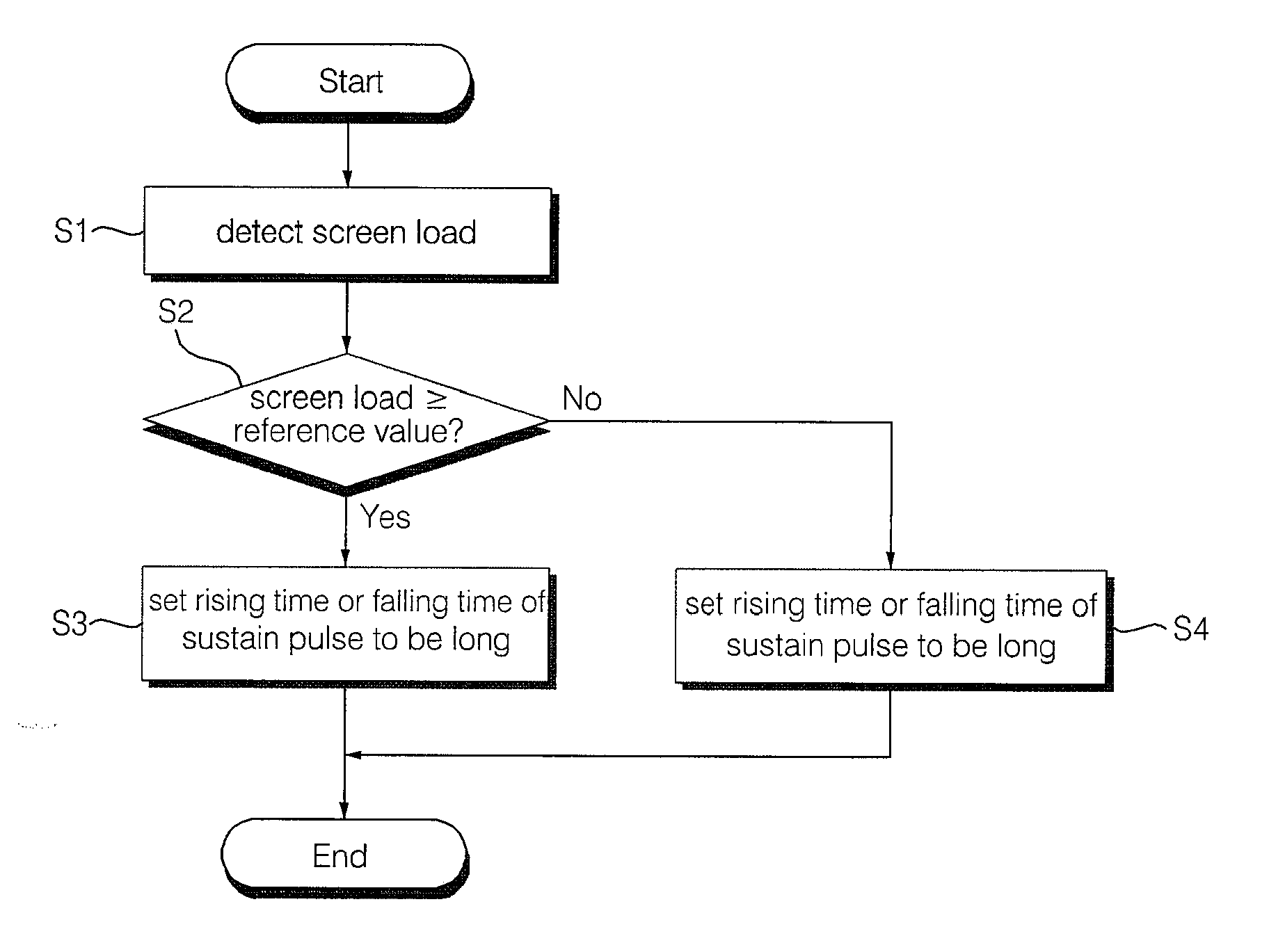
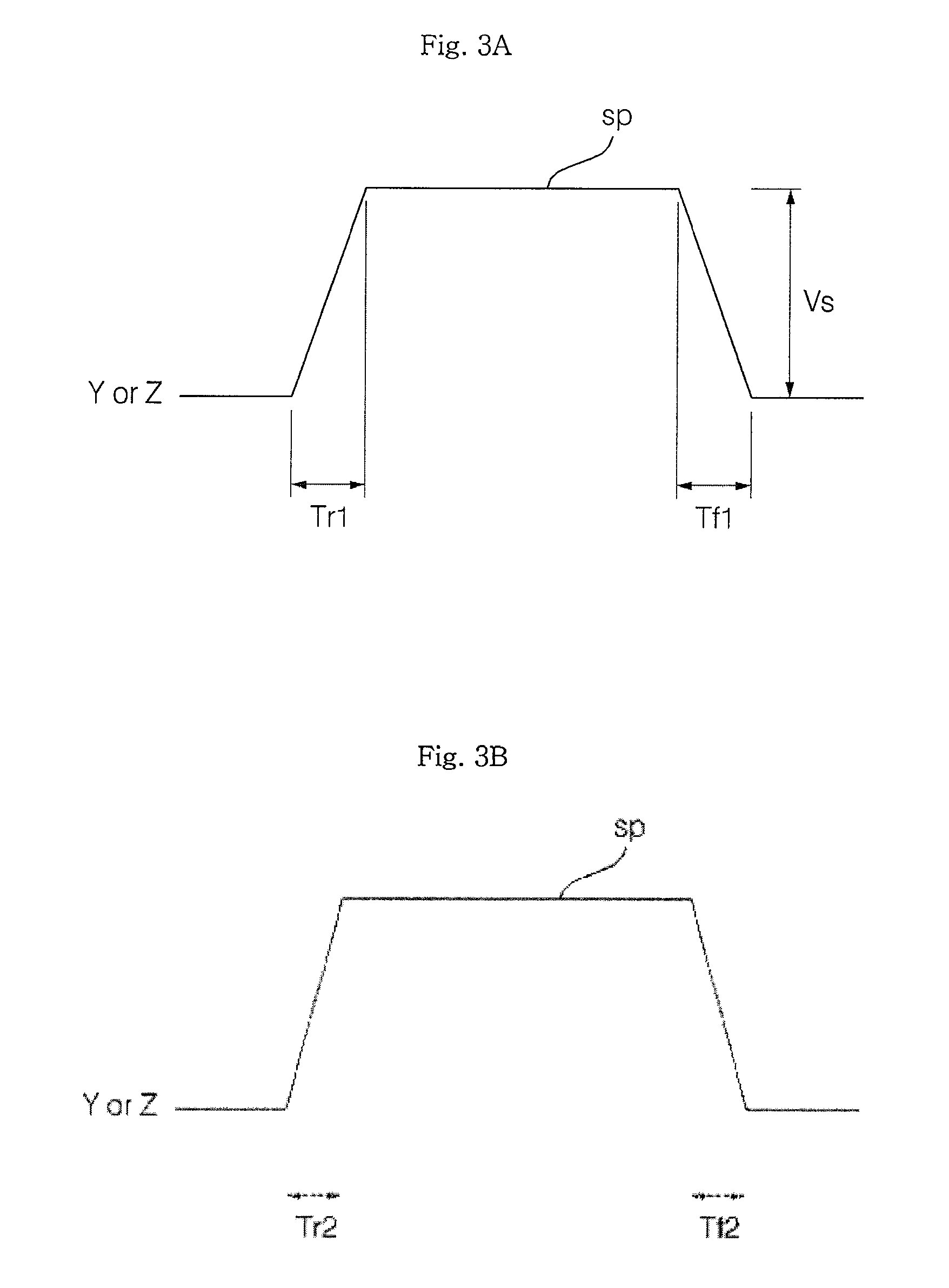
[0020] Another object of the present invention is to provide a plasma display device which can secure discharge efficiency and brightness although a screen load is large by extending a rising time or a falling time of a sustain pulse applied during a sustain period when a screen load is large, compared to when a screen load is small, and a driving method thereof.
[0022] At this time, the driver may detect a displayed screen load and enhance discharge efficiency by adjusting a rising time or a falling time of the sustain pulse to be long when the displayed screen load is a predetermined reference value or more, compared to when the screen load is less than the reference value.
[0025] When a rising time or a falling time of a sustain pulse is shortened, a resistance of an internal element of a plasma display device is reduced and damage due to discharge can be reduced. When a rising time or a falling time of a sustain pulse is shortened, a luminescent spot characteristic can be improved by reducing a difference of wall charges between a cell in which discharge occurs and a cell in which discharge does not occurs.
[0026] Therefore, as a rising time or falling time of the sustain pulse is extended when a screen load is large and a rising time or a falling time of the sustain pulse is shortened when the screen load is small, an afterimage and brightness of a plasma display device are improved, so that an image quality characteristic can be enhanced.

Problems solved by technology

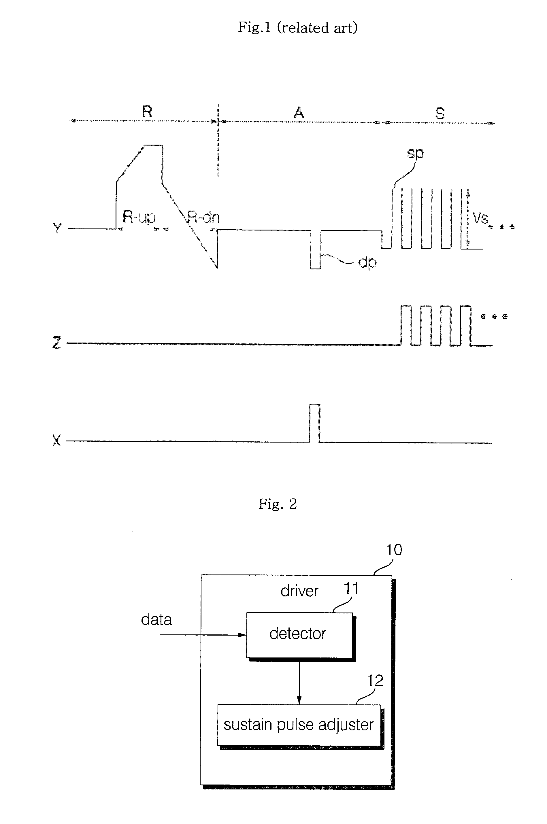
When a screen is displayed, if a screen load is in a range of over 40 to 50% of full white, there is a problem that an excess current flows in a driver provided to apply an address pulse or a sustain pulse (sp).

Method used


Image

  • Plasma display device and operating method of the same
  • Plasma display device and operating method of the same
  • Plasma display device and operating method of the same

Examples


Embodiment Construction

[0039] Hereinafter, exemplary embodiments of a plasma display device and a driving method thereof according to the present invention will be described in detail with reference to the accompanying drawings. There are many exemplary embodiments of a plasma display device and a driving method thereof according to the present invention and hereinafter, the most preferable embodiment will be described. However, a basic structure of the plasma display device and the driving method thereof is the same as that of the above-mentioned prior art and thus detailed description thereof will be omitted.

[0040]FIG. 2 shows a construction of a conventional plasma display device and FIG. 3a or 3b shows a sustain pulse according to a first embodiment of the present invention. First, a plasma display device according to the present invention will be described with reference to FIG. 2.

[0041] A general three-electrode surface-discharge plasma display device has a first electrode and a second electrode i...


PUM


Abstract

There is provided a plasma display device which can improve a brightness characteristic and a driving method thereof, where a screen load is detected and a rising time or a falling time of a sustain pulse changes depending on the detected screen load. A rising time or a falling time of a sustain pulse is extended when the screen load is large, compared to when the screen load is small. Therefore, brightness and discharge efficiency of a plasma display device can be enhanced when the screen load is large and a voltage margin can be enhanced while having a stable brightness characteristic when the screen load is small, so that a picture quality characteristic can be improved while enhancing driving efficiency of a plasma display panel.

Description

BACKGROUND OF THE INVENTION [0001] 1. Field of the Invention [0002] A plasma display device displays an image including a character or a graphic by allowing a phosphor to emit light by ultraviolet rays of 147 nm generating upon discharging of He+Xe, Ne+Xe, and He+Ne+Xe gas. Such a plasma display device can be easily manufactured in flat and large and provides a greatly improved image quality thanks to the recent technical development. [0003] A three-electrode AC surface-discharge plasma display device has three electrodes in each discharge cell, lowers a voltage required for discharge using wall charges accumulated on a surface upon discharging, and protects electrodes from sputtering generated by discharge, so that it has an advantage of a low voltage drive and a long lifetime. [0004] Such a plasma display device performs sustain discharge by selecting a discharge cell by address discharge and applying a sustain pulse with the selected discharge cell, so that an image is displayed....

Claims


Application Information

Patent Timeline
IPC IPC(8): G09G3/28G09G3/288G09G3/294
CPCG09G3/2942G09G3/2946G09G2310/066G09G2360/16B60H1/00978B60H1/32
Inventor AHN, YOUNG JOONLEE, SANG KOOK
Owner LG ELECTRONICS INC
Learn More