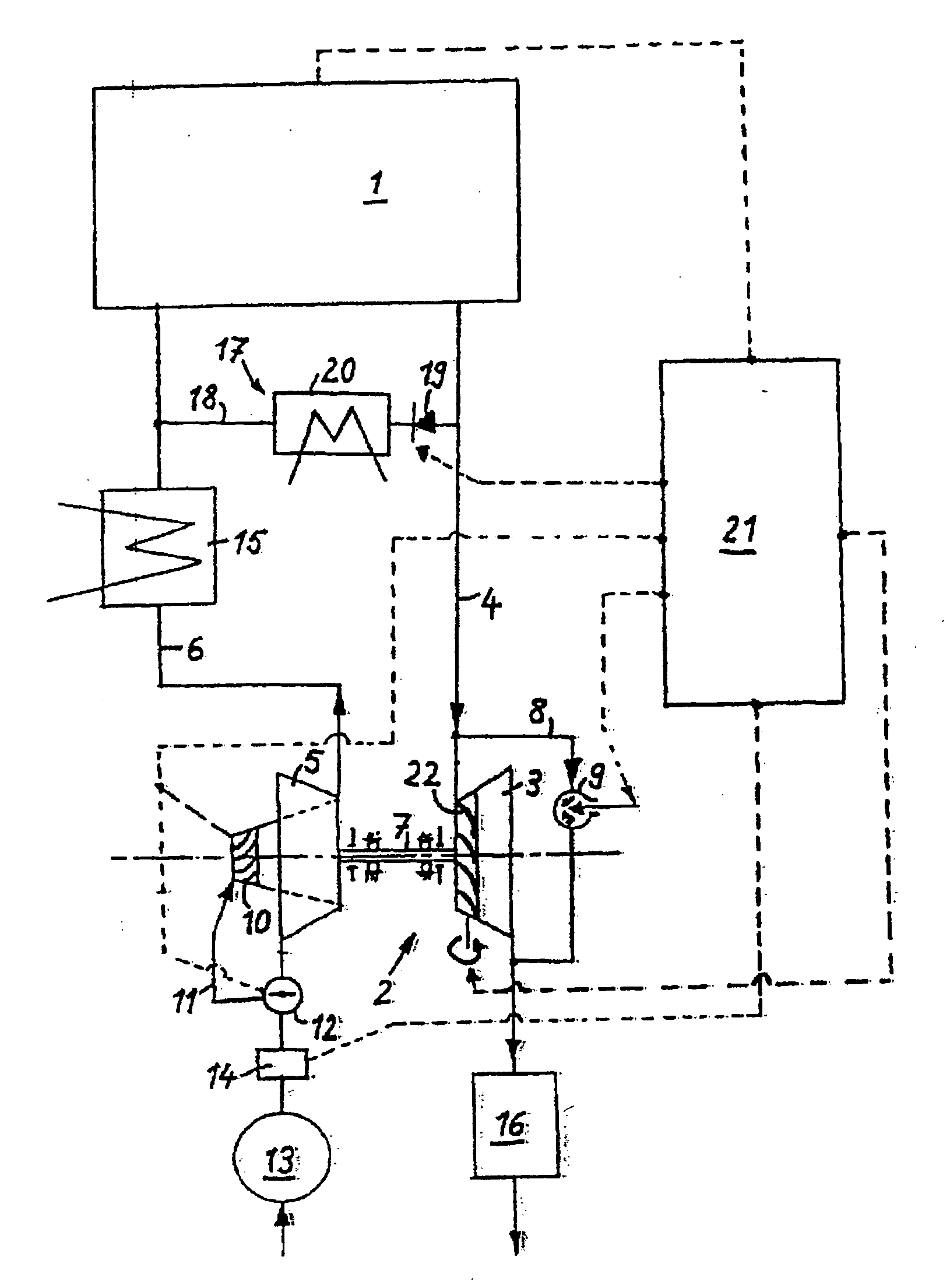
[0007] This defines a directly dependent relationship between the fast running speed of the exhaust gas turbocharger which is to be set and the narrowest turbine cross section, which is reached in the back-up position or at least close to the back-up position of the variable turbine geometry. It is in this way possible, in particular in cold-air turbine mode of the compressor, in which there is a pressure drop across the compressor, which is utilized to drive the compressor
impeller, to operate both the compressor and the cold-air turbine in the region of their optimum efficiencies and also to operate the exhaust gas turbine in the region of its optimum efficiency. Increasing the turbine pressure ratio also increases the isentropic
expansion rate and therefore also the turbine power of the exhaust gas turbine, which means that despite the higher rotational speed of the exhaust gas turbine, the optimum efficiency range is not departed from, and in particular an undesired
ventilation mode, in which energy is consumed, is avoided.
[0008] In principle, these measures make it possible to dispense with an additional drive for the charger without the risk of efficiency losses or a drop in the charger rotational speed. Rather, the charger rotational speed is kept at an approximately constant and high level. Nevertheless, it may be expedient to provide an additional drive.
[0009] The compressor of the exhaust gas turbocharger expediently has an additional passage, which is formed separately from the compressor inlet passage and opens out radially into the compressor inlet passage at the compressor
impeller. The
combustion air
stream which is to be supplied via the additional passage is adjustable, with the combustion air
stream which is to be supplied being passed via the additional passage in particular in the lower load / speed range of the internal combustion engine, this air
stream then striking the compressor
impeller blades radially and imparting a driving
momentum to them. Due to the pressure gradient across the compressor, combustion air is sucked in from the environment. The compressor which is operated in cold-air turbine mode makes a contribution to maintaining the charger rotational speed. As the load or speed of the internal combustion engine increases, it is possible to reduce the supply of air across the additional passage and ultimately to eliminate this supply of air altogether, so that the combustion air takes the normal path via the compressor inlet passage and strikes the compressor impeller at the end side. At higher loads and speeds of the internal combustion engine, the compressor is operated in compressor mode, with the combustion air which is supplied being compressed to an increased boost pressure.
[0010] To eliminate the risk of excessive rotational speeds in the rotor of the exhaust gas turbocharger, the variable turbine geometry, if the exhaust gas turbocharger rotational speed exceeds an upper
limit value, can be adjusted in the direction of its open position until the incoming flow exerts a braking action on the
turbine wheel, after which the exhaust gas turbine consumes energy and has a braking action on the exhaust gas turbocharger rotational speed. This operating mode is also known as
ventilation mode of the exhaust gas turbine. The risk of excessive rotational speeds may occur in particular in the event of load changes in the internal combustion engine from a
high load towards a low part-load, which is associated with a considerable pressure drop in the intake section immediately upstream of the cylinder inlets. As a result, the load on the compressor is greatly relieved and it suddenly shifts to cold-air turbine mode, in which the compressor delivers drive energy to the rotor. At the same time, the hot
exhaust manifold is responsible for supplying considerable energy to the exhaust gas, with the result that the exhaust gas turbine is also briefly providing further drive energy, which overall would lead to an unacceptably
high rise in the exhaust gas turbocharger rotational speed. To avoid this, the variable turbine geometry of the exhaust gas turbocharger is opened as quickly as possible to a sufficient extent for the efficiency of the exhaust gas turbine to become negative and the turbine to be operated in
ventilation mode, in which energy is consumed. The resulting,
negative power resulting from bearing friction and braking power of the exhaust gas turbine must be greater than the driving power of the compressor which is being operated in cold-air turbine mode.
[0011] After the braking influence of the exhaust gas turbine has reduced the exhaust gas turbocharger rotational speed to a permissible level, the variable turbine geometry can return to the position appropriate for the current operating mode, i.e. low loads and speeds of the internal combustion engine can in particular be moved back towards the back-up position.


