External combustion rotary piston engine

a rotary piston, external combustion technology, applied in the direction of engine components, sealing arrangements, combustion engines, etc., can solve the problems of pistons and connecting rods, maintenance problems, temperature and pressure of gas still far above the surrounding atmosphere, etc., to achieve low nox emissions, simple manufacturing, and efficient and reliable operation

Inactive Publication Date: 2006-09-07
REVOLUTION ENGINE CORP
View PDF11 Cites 26 Cited by
  • Summary
  • Abstract
  • Description
  • Claims
  • Application Information

AI Technical Summary

Benefits of technology

[0011] It is an object of the present invention to provide an engine which is relatively simple to fabricate, which is relatively efficient and reliable in operation and which produces relatively low NOx emissions. This object, amongst others, is met by the present invention, an engine for use with a load.
[0018] The combuster means is adapted to receive varying amounts of fuel, thereby to cause the power transfer means to drive the load with varying amounts of power in use.
[0019] The combuster means is adapted to receive varying amounts of fuel, thereby to cause the power transfer means to drive the load with varying amounts of power in use.
[0025] The relative ratio of V1 versus V2 will determine the nominal minimum compression ratio of the engine. This is dictated by the geometry of the engine and will not vary. On the other hand, the difference between T1 and T2 will be due both to the temperature increase during compression, and due to the heat added by the fuel. When the engine is under a light load, less fuel will be needed, less heat will be generated and less work will be needed to run the compressor section. This variable compression ratio means that the engine will only do as much work compressing the incoming air as is required by torque demand of the engine, that is, the engine will spontaneously adjust its compression ratio to engine load, thereby to improve operating efficiency. Another consequence of this arrangement is that the combustion temperature at partial fuel loads will be lower than that at the maximum condition, so as to reduce the tendency of the engine to produce NOx emissions.
[0036] The combuster is adapted to receive varying amounts of fuel, thereby to cause the power transfer means to drive the load with varying amounts of power in use.

Problems solved by technology

A problem common to this type of engine is that after the fuel burns, and the resulting hot gas drives the piston to the end of the power stroke, the temperature and pressure of the gas are still far above that of the surrounding atmosphere.
This heat and pressure are both manifestations of wasted energy.
A further problem common to this type of engine derives from the fact that the pistons and connecting rods must reverse direction of motion many times a minute.
The forces required to overcome the inertia involved require substantial engineering, and generate vibration and wear, leading to maintenance issues.
A further problem common to this type of engine is the efficiency losses associated with converting a reciprocating linear motion into rotational power.
Little useful work is done before 30 degrees from TDC or after 135 from TDC, so a considerable amount of efficiency is lost.
A yet further problem common to this type of engine is that the high combustion temperatures under which this engine operates result in relatively high NOx emissions.
However, the gerotors are difficult to fabricate.
Further, the servos add complexity to the design, with attendant maintenance issues.
However, the need to employ screw-shaped rotors adds to cost, and the engine is prone to the production of high NOx emissions, resultant from the high temperatures employed.

Method used


Image

  • External combustion rotary piston engine
  • External combustion rotary piston engine
  • External combustion rotary piston engine

Examples


first preferred embodiment

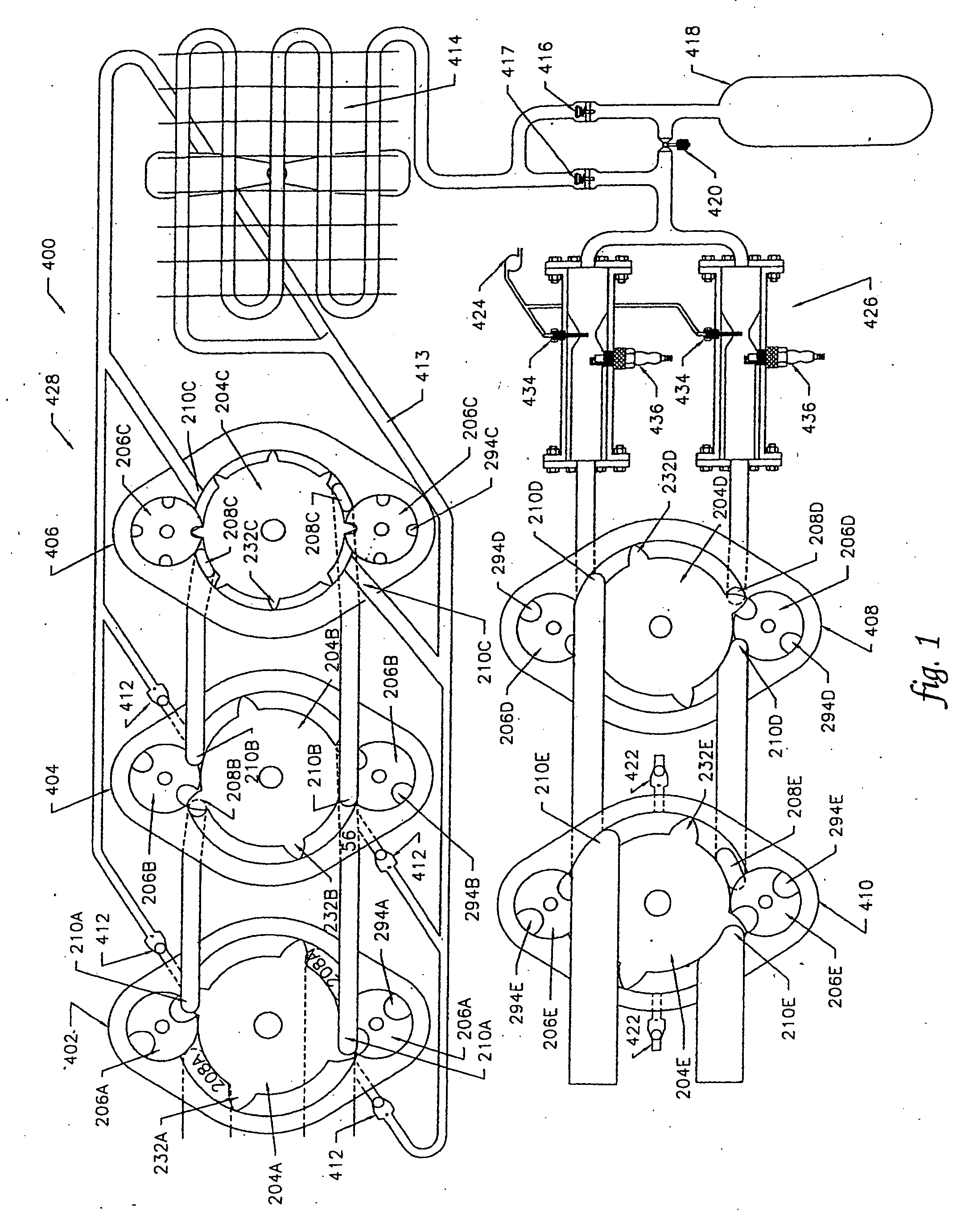
[0132] Turning now to the engine 400 constructed according to the aforementioned first preferred embodiment, a schematic overview of same is shown as FIG. 1.

[0133] From the overview, this engine 400 will be seen to comprise a first compression stage 402, a second compression stage 404, a third compression stage 406, a positive displacement air motor 408 and a positive displacement gas expander 410. Each of these elements take the form of a rotary device as previously described, and in fact, the exemplary rotary device described is one and the same as that of the second compression stage 404. As these rotary devices are generally similar in operation and structure, a detailed description of each is not provided herein. Rather, it should simply be understood that equivalent structures in each of the rotary devices share a common numeric identifier, and that the alphabetic identifier of the structures denote the device in question, as follows: first compression stage (A), second compr...

second preferred embodiment

[0161] A second preferred embodiment of an engine according to the present invention is illustrated in FIGS. 21-26. Components of this engine which correspond to those of the first preferred embodiment are provided with identical reference numerals. As will be evident to persons of ordinary skill in the art, this engine is generally similar to that of the first preferred embodiment, and thus, a detailed description of its components and operation is neither needed nor provided herein. Rather, for simplicity, only the differences in structure and operation are herein set out.

[0162] From the standpoint of structure, this engine lacks a third compression stage, and includes only two pistons, in contrast to the previous embodiment, wherein five pistons were used. Further, wherein in the previous embodiment the gate rotors were disposed 180° apart from one another relative to the drive shaft, herein, the gate rotors are about 130° apart from one another, such that the chambers defined o...


PUM


Abstract

An engine (400) is disclosed and comprises: a compressor (428) which periodically defines a chamber and carries out a pressurization process wherein the chamber volume is decreased to produce pressurized air; a combuster (426) which combusts fuel with the pressurized air to produce primary exhaust; an air motor (408) which is driven by the primary exhaust to produce power and secondary exhaust; an expander (410) which expands the secondary exhaust to produce tertiary exhaust and power; and a shaft (314) which directs power produced by the motor (408) and the expander (410) to the compressor (428) and any load. The combuster (426) is adapted to receive varying amounts of fuel, thereby to vary the power to the load. The compressor (428), during pressurization. releases air from the chamber such that the chamber pressure during pressurization and the primary exhaust pressure is substantially constant at steady state conditions, said constant being a function of the load being driven by the power.

Description

TECHNICAL FIELD [0001] The following invention relates to engines, and more specifically, to variable compression engines. BACKGROUND ART [0002] In a traditional piston-in-cylinder internal combustion engine, there are four “strokes”: intake; compression; power (expansion); and exhaust. In the intake stroke, the piston commences motion at a point proximal to the head of the cylinder and travels to a point distal to the head of the cylinder, creating an expanding void in the cylinder between the piston and the cylinder head which is suitably ported to atmosphere to fill with ambient air during such travel. At the end of the intake stroke, fluid communication between the atmosphere and the cylinder is arrested. In the compression stroke, the piston reverses direction in the cylinder, thereby compressing the air contained therein. When the air is highly compressed (at the end of the compression stroke) fuel mixed with the compressed air is ignited, to create combustion. In the power st...

Claims


Application Information

Patent Timeline
Patent Type & Authority Applications(United States)
IPC IPC(8): F02B53/00F02B53/08F02B53/04F01C1/08F01C1/20F01C11/00F01C19/00
CPCF01C1/084F01C1/20F01C11/004F01C19/00F01C19/10
Inventor CONNERS, JAMES M.
Owner REVOLUTION ENGINE CORP
Why Eureka
Try Eureka