
Method for measuring formation properties with a formation tester

a technology of formation properties and test tubes, which is applied in the field of oil and gas exploration, can solve the problems of inability to communicate in real time with the tools, the current limitations of telemetry, and the duration of the test, so as to reduce the initial pressure

Active Publication Date: 2006-08-31
SCHLUMBERGER TECH CORP
View PDF3 Cites 10 Cited by
  • Summary
  • Abstract
  • Description
  • Claims
  • Application Information

AI Technical Summary

Benefits of technology

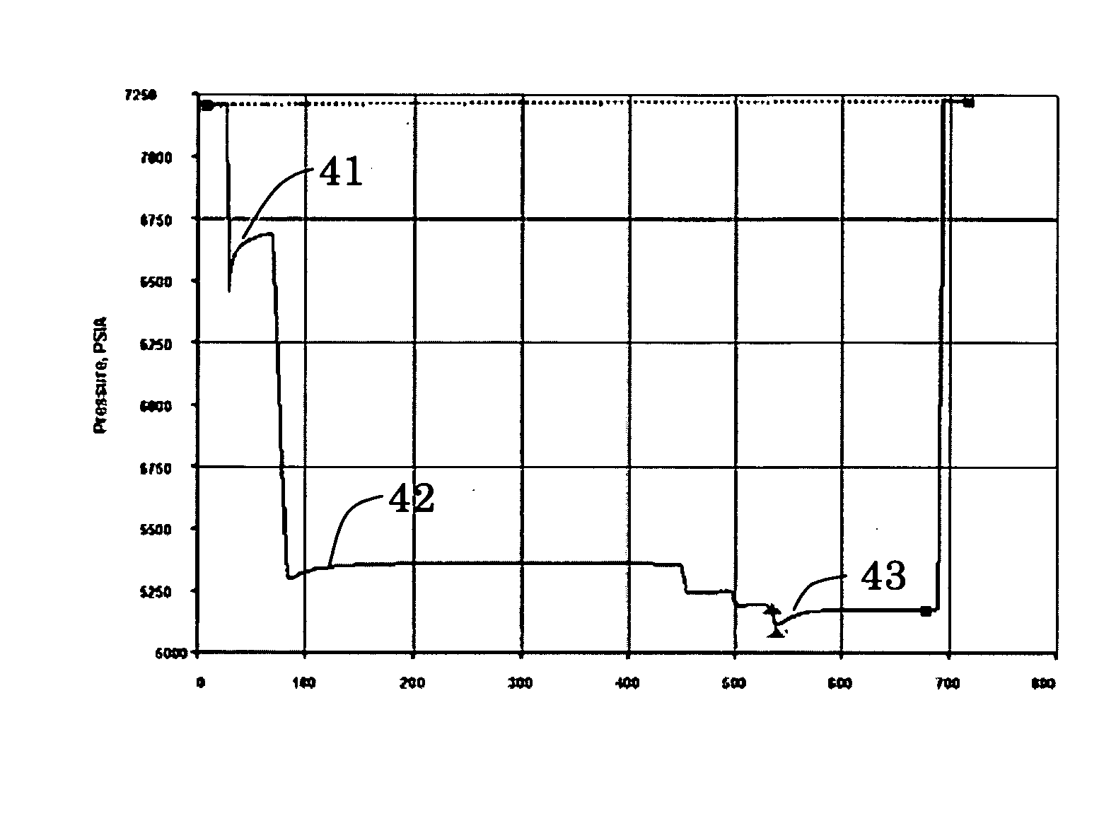
[0019] In a further aspect of the invention, a method is disclosed for estimating a formation pressure using a formation tester disposed in a wellbore penetrating a formation, said method comprising: (a) establishing fluid communication between a pretest chamber in the downhole tool and the formation via a flowline, the flowline having an initial pressure therein; (b) moving a pretest piston in a controlled manner in the pretest chamber to reduce the initial pressure to a drawdown pressure during a drawdown phase; (c) terminating movement of the piston to permit the drawdown pressure to adjust to a stabilized pressure during a build-up phase and measuring simultaneously in relation to time, pressure P(t) and temperature T(t) in the pretest chamber; (d) extracting an index i(t) dependent of the pressure P(t) and the temperature T(t) informing on the build-up phase; (e) analyzing index i(t) an...

Problems solved by technology

Because formation testing operations are used throughout drilling operations, the duration of the test and the absence of real-time communication with the tools are major constraints that must be considered.
The problems associated with real-time communication for these operations are largely due to the current limitations of the telemetry typically used during drilling operations, such as mud-pulse telemetry.
Limitations, such as uplink and downlink telemetry data rates for most logging while drilling or measurement while drilling tools, result in slow exchanges of information between the downhole tool and the surface.
For example, a simple process of sending a pretest pressure trace to the surface, followed by an engineer sending a command downhole to retract the probe based on the data transmitted may result in substantial delays which tend to adversely impact drilling operations.
Furthermore, delays also increase the possibility of tools becoming stuck in the wellbore.
Nevertheless, in this automatic mode, some steps are sometimes redundant or useless, increasing the time spends on non useful information during this limited period of time and increasing the possibility of tool becoming stuck in the wellbore.

Method used


Image

  • Method for measuring formation properties with a formation tester
  • Method for measuring formation properties with a formation tester
  • Method for measuring formation properties with a formation tester

Examples


Embodiment Construction

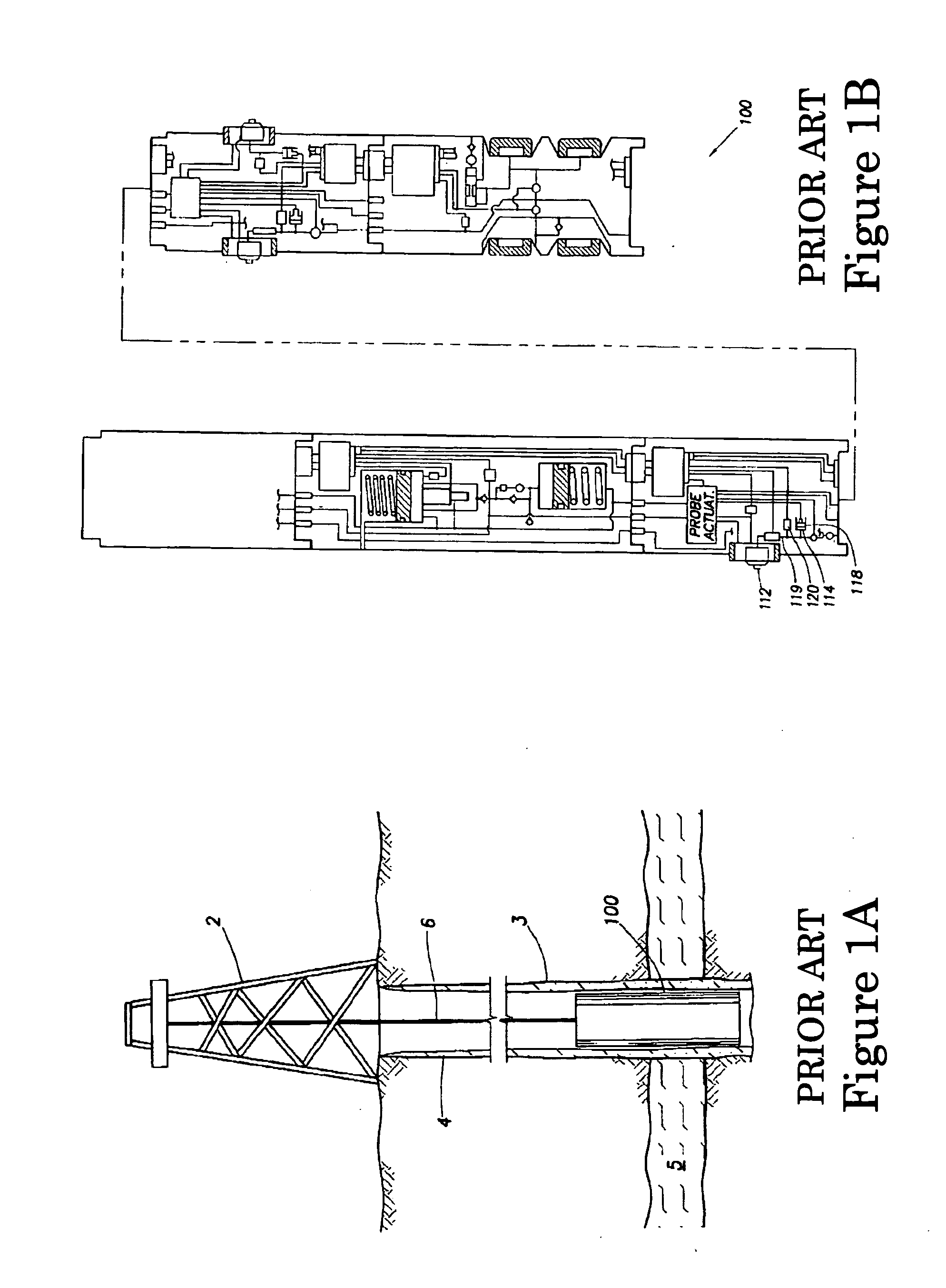
[0036] An embodiment of the present invention relating to a method for estimating formation properties (e.g. formation pressures and mobilities) may be applied with any formation tester known in the art, such as the tester described with respect to FIGS. 1A and 1B. Other formation testers may also be used and / or adapted for embodiments of the invention, such as the wireline formation tester of U.S. Pat. Nos. 4,860,581 and 4,936,139 issued to Zimmerman et al. and the downhole drilling tool of U.S. Pat. No. 6,230,557 B1 issued to Ciglenec et al. The method of the present invention is an improvement of the method of U.S. Patent Application No. 2004 / 00457006 which discloses a method including an investigation phase and a measurement phase to estimate formation properties.

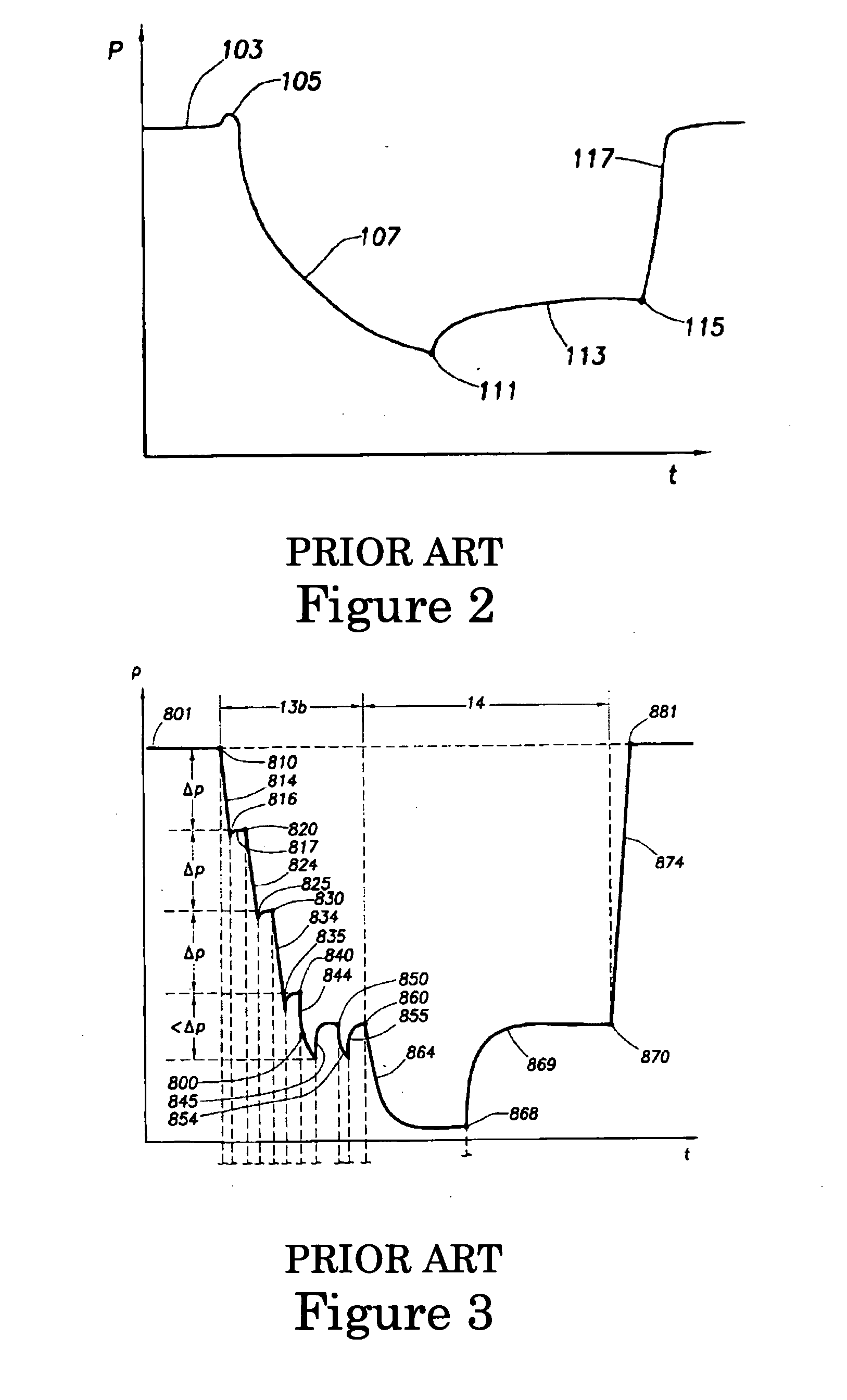
[0037] In U.S. Patent Application No. 2004 / 00457006, the method consists in performing an investigation phase 13b with several drawdown steps. Referring to FIG. 3, the method comprises the step of starting the drawdown...


PUM


Abstract

A method is disclosed for estimating a formation pressure using a formation tester disposed in a wellbore penetrating a formation, said method comprising: (a) establishing fluid communication between a pretest chamber in the downhole tool and the formation via a flowline, the flowline having an initial pressure therein; (b) moving a pretest piston in a controlled manner in the pretest chamber to reduce the initial pressure to a drawdown pressure during a drawdown phase; (c) terminating movement of the piston to permit the drawdown pressure to adjust to a stabilized pressure during a build-up phase and measuring simultaneously in relation to time, pressure P(t) and temperature T(t) in the pretest chamber; (d) extracting an index i(t) dependent of the pressure P(t) and the temperature T(t) informing on the build-up phase; (e) analyzing index i(t) and repeating steps (b)-(d) or going to step (f); (f) determining the formation pressure based on a final stabilized pressure in the flowline. And more generally a method could be used for estimating type of a build up pressure phase, the build up pressure phase being done after a drawdown pressure phase, said both drawdown and build up phases being done to determine formation pressure using a formation tester disposed in a wellbore penetrating a permeable formation, said permeable formation being able to create a formation flow, said method being characterized by using an index to determine the contribution of formation flow on the pressure build up phase.

Description

FIELD OF THE INVENTION [0001] The present invention relates generally to the field of oil and gas exploration. More particularly, the invention relates to methods for determining at least one property of a subsurface formation penetrated by a wellbore using a formation tester. DESCRIPTION OF THE PRIOR ART [0002] Over the past several decades, highly sophisticated techniques have been developed for identifying and producing hydrocarbons, commonly referred to as oil and gas, from subsurface formations. These techniques facilitate the discovery, assessment, and production of hydrocarbons from subsurface formations. [0003] When a subsurface formation containing an economically producible amount of hydrocarbons is believed to have been discovered, a borehole is typically drilled from the earth surface to the desired subsurface formation and tests are performed on the formation to determine whether the formation is likely to produce hydrocarbons of commercial value. Typically, tests perfo...

Claims


Application Information

Patent Timeline
IPC IPC(8): E21B47/06E21B21/08
CPCE21B49/008
Inventor MANIN, YVESLIGER, FRANCOIS
Owner SCHLUMBERGER TECH CORP
Learn More