Analog filter

a filter and analog technology, applied in the field of analog filters, can solve the problems of distorted output waveform, complex constitution, and distorted output waveform, and achieve the effects of preventing phase distortion, less distortion in output waveform, and conspicuous enhancement of sound quality

Inactive Publication Date: 2006-08-24
NSC CO LTD
View PDF5 Cites 0 Cited by
  • Summary
  • Abstract
  • Description
  • Claims
  • Application Information

AI Technical Summary

Benefits of technology

[0021] This invention is composed of the technical means as above, in which over-sampling and the moving average or convolution operation are conducted to interpolate the ΔΣ-modulated discrete data so that the envelope of the filter output may be a sampling function of finite carrier that converges to zero at finite sampling points to prevent phase distortion of a low pass filter and a discretization error due to the sinc function and produce a smooth analog signal with less distortion in the output waveform. Accordingly, if the analog filter of the invention is applied to the acoustic equipment, the sound quality can be conspicuously enhanced as compared with the conventional acoustic equipment.
[0022] With this invention, as compared with a conventional circuit for the moving average operation or convolution operation, the number of stages of the sample hold circuits and the number of adders can be significantly reduced, thereby simplifying the configuration.

Problems solved by technology

However, when the low pass filter was used, there was a problem that the output waveform was distorted due to a phase distortion of the low pass filter.
However, since this sinc function converges to zero toward ±∞, a discretization error occurs in the arithmetic operation and a distorted output waveform is produced.
Also, there was another problem that the constitution was quite complex.

Method used


Image

  • Analog filter
  • Analog filter
  • Analog filter

Examples


first embodiment

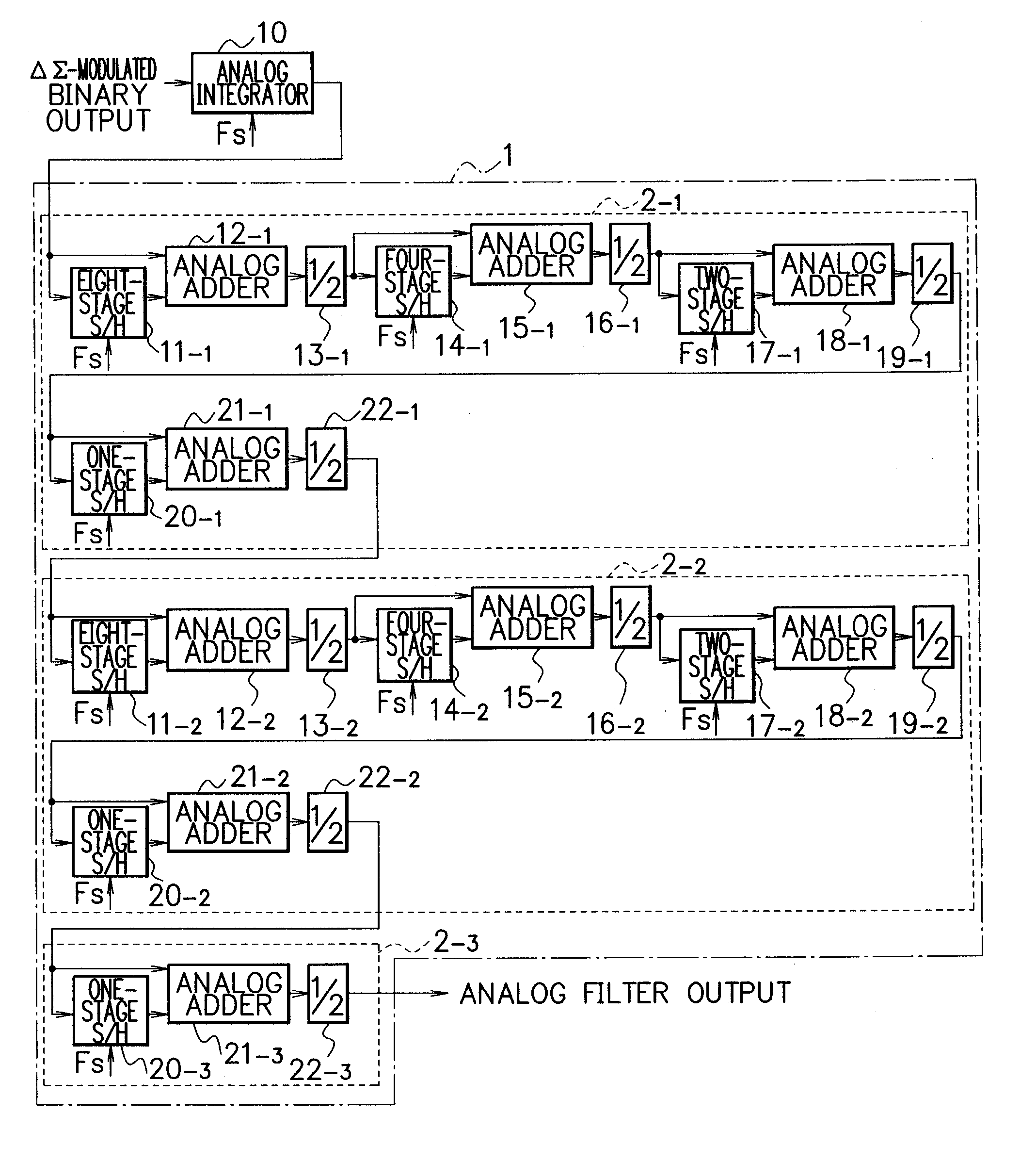
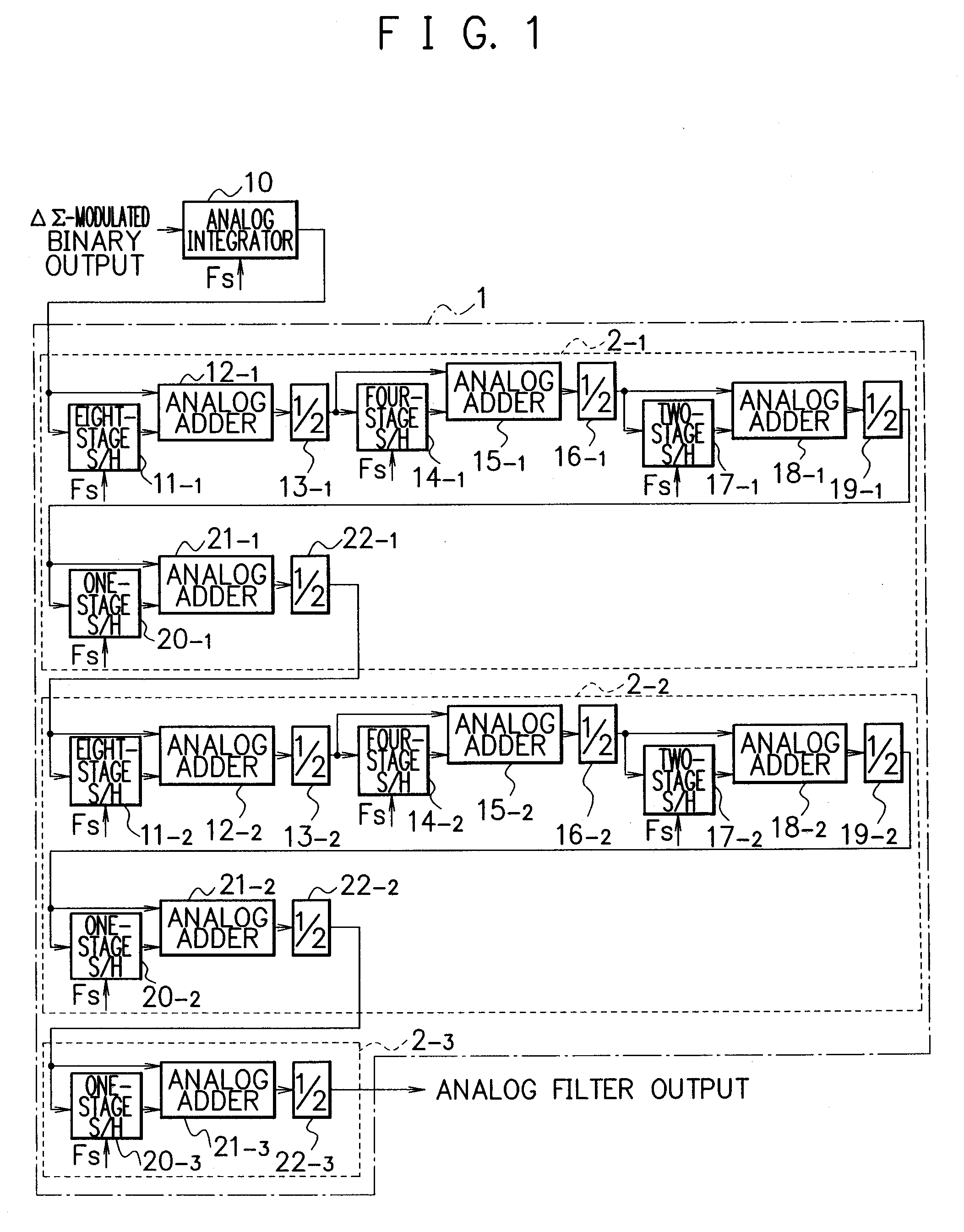
[0034] An analog filter according to a first embodiment of the invention provides an analog signal having a smoother and less distorted waveform by over-sampling in certain times, and performing the moving average or convolution operation (hereinafter referred to as convolution) on individual ΔΣ-modulated binary signal (one bit).

[0035]FIG. 1 is a block diagram showing one configuration example of the analog filter according to this embodiment. FIG. 2 and FIG. 3 are diagrams for explaining an operation principle of the analog filter according to this embodiment. First of all, the operation principle will be described below using FIG. 2 and FIG. 3.

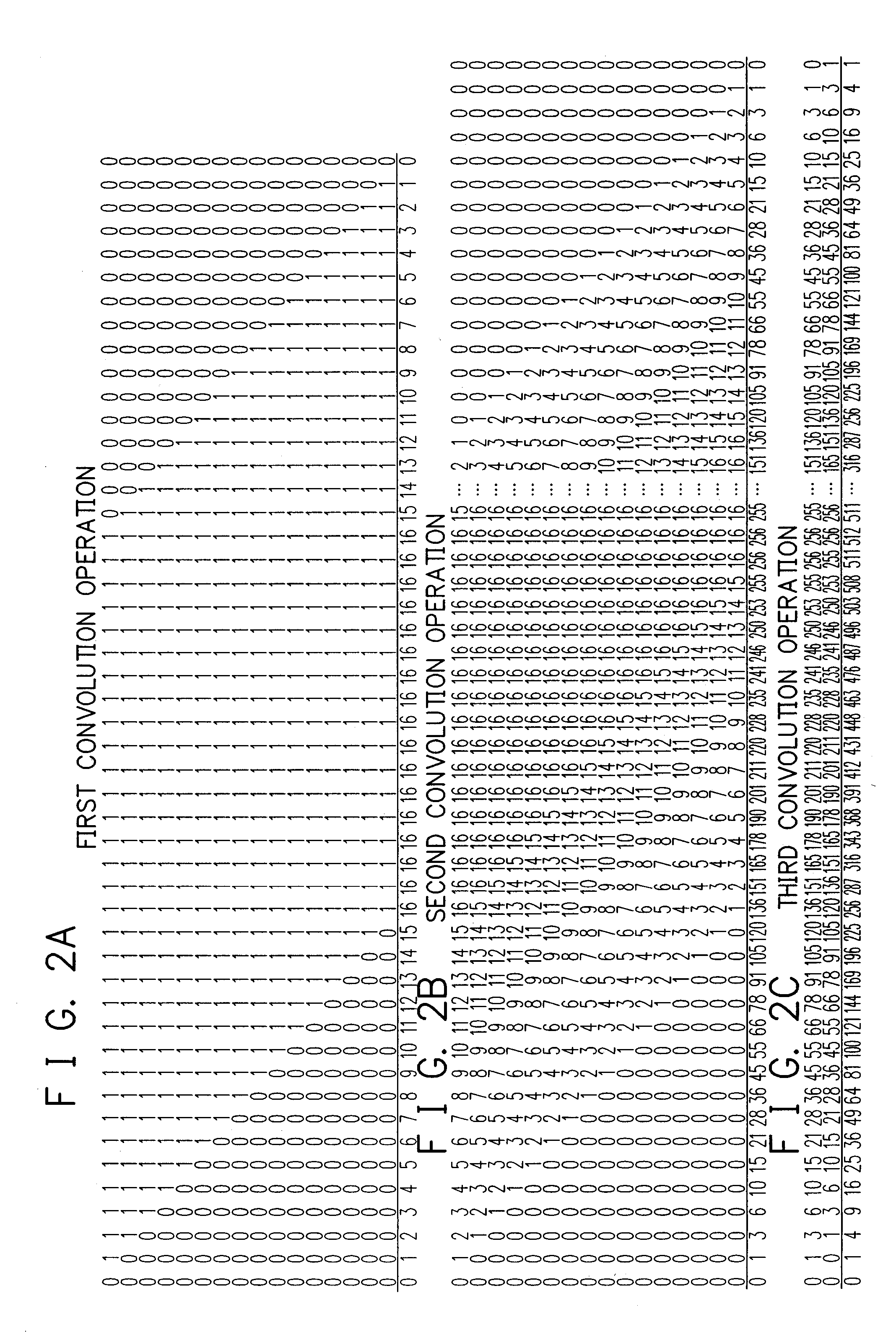
[0036]FIG. 2 and FIG. 3 show a process of converting a single rectangular wave having a time width of 2nT (n=16 in FIG. 2) and an amplitude 1 into an analog signal, with a unit time determined by a sampling frequency f being T (=1 / f).

[0037]FIG. 2A shows a processed example of over-sampling in 2n times and the first convolution operation. ...

second embodiment

[0062] A second embodiment of the invention will be described below.

[0063] An analog filter according to the second embodiment of the invention provides an analog signal having a smoother waveform by weighting a ΔΣ-modulated binary signal (one bit signal) with a digital fundamental waveform corresponding to a predetermined sampling function as described below, and performing the convolution operation as described in the first embodiment on its output signal.

[0064]FIG. 7 is a block diagram showing one configuration example of the analog filter according to this embodiment, and FIG. 8 is a timing chart showing the operation timing. Also, FIG. 9 is a diagram showing the digital fundamental waveform, and FIG. 10 is a graph representing a waveform obtained as a result of passing the digital fundamental waveform through the analog filter. First of all, the operation principle will be described below using FIG. 9 and FIG. 10.

[0065] A digital fundamental waveform as shown in FIG. 9 is fu...


PUM


Abstract

An analog filter includes a first arithmetic operation section 2-1 having a plurality of sets of processing circuit being cascade connected, each processing circuit having an S / H circuit of plural stages for holding a ΔΣ-modulated signal and an analog adder for adding the input and output signals of the S / H circuit, in which the number of stages of the S / H circuits 11-1, 14-1, 17-1 and 20-1 decreases toward the end of cascade connection, and a second arithmetic operation section 2-2 configured in the same way, which are cascade connected. By using such an analog filter, over-sampling and convolution of a ΔΣ-modulated signal are conducted so that the envelope of the filter output may be a quadratic curve of finite carrier that converges to zero at finite sampling points to prevent phase distortion of an LPF and a discretization error due to a conventional function. Compared with a conventional circuit for over-sampling and convolution, the number of stages of the S / H circuits and the number of adders are small.

Description

CROSS REFERENCE TO RELATED APPLICATIONS [0001] This application is a Continuation under 35 U.S.C. §120 of U.S. application Ser. No. 10 / 203,004 filed on Aug. 5, 2002. application Ser. No. 10 / 203,004 is a National Stage Entry under 35 U.S.C. §371 of International Application PCT / JP01 / 010670 filed on Dec. 6, 2001, and which claims priority to Japanese Application 2000-372222 filed on Dec. 7, 2000. The entire contents of each of these applications are incorporated herein by reference.BACKGROUND OF THE INVENTION [0002] 1. Field of the Invention [0003] The present invention relates to an analog filter that is suitably used as a filter for smoothing a ΔΣ-modulated signal, for example. [0004] 2. Description of the Related Art [0005] A ΔΣ-modulation is a method for encoding an analog signal with a variation in the data for the immediately preceding data at each sampling point sampled at each timing of a predetermined sampling frequency in converting an analog signal into a digital signal. Th...

Claims


Application Information

Patent Timeline
Patent Type & Authority Applications(United States)
IPC IPC(8): G06G7/02H03H11/04H03H15/02H03H17/02H03M3/02H04B14/06
CPCH03H11/04H03H17/02H03H17/026
Inventor KOYANAGI, YUKIO
Owner NSC CO LTD
Why Eureka
Try Eureka