
Method and apparatus for communicating computer data from one point to another over a communications medium

a technology of communication medium and communication method, applied in the direction of digital transmission, sonic/ultrasonic/infrasonic transmission, baseband system details, etc., can solve the problems of increasing increasing the cost of manufacturing, and prior systems that have proved limited in their capabilities, so as to improve the signal rate or the number of wires, clear and fast data transfer, and remove synchronization errors

Inactive Publication Date: 2007-07-24
MORGAN STANLEY
View PDF50 Cites 43 Cited by
  • Summary
  • Abstract
  • Description
  • Claims
  • Application Information

AI Technical Summary

Benefits of technology

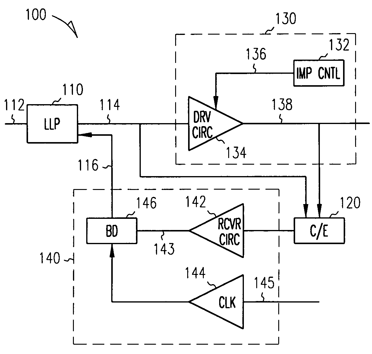
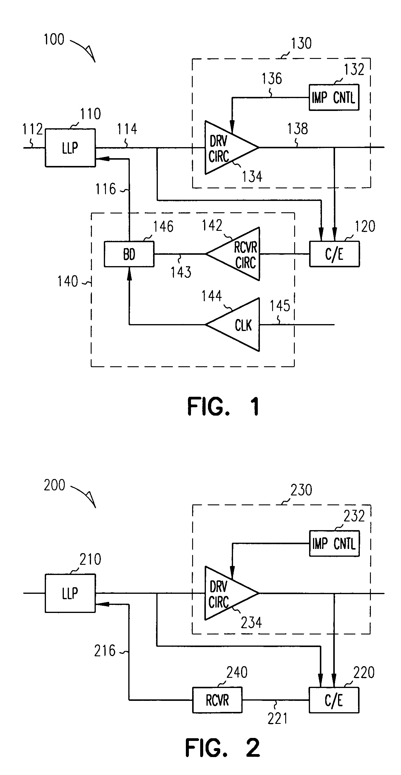
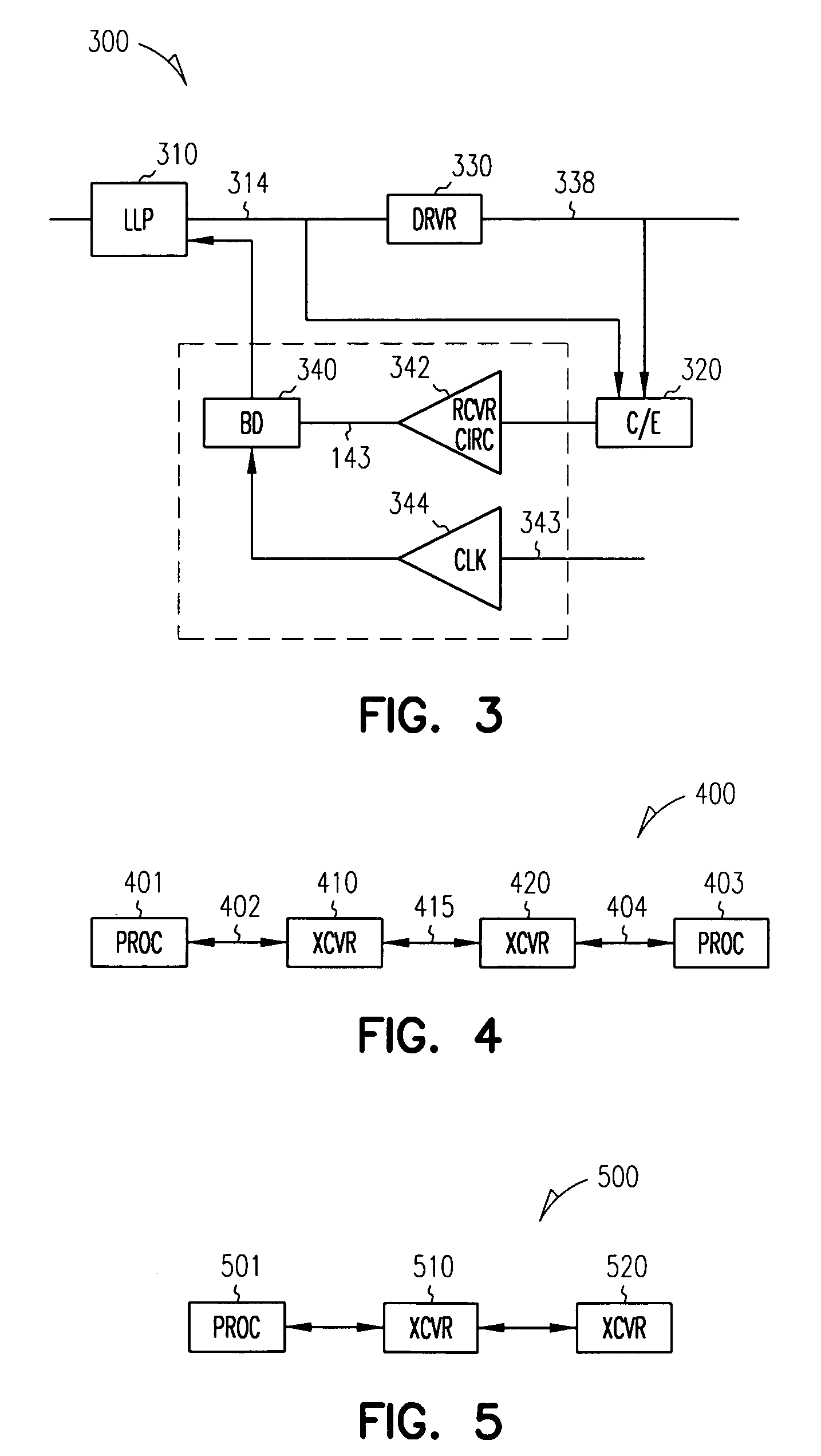
[0007]The link level protocol provides logic for DC-free signal encoding and recovery. In addition, the link level protocol supports features such as CRC error detection and message resend in order to accommodate bit errors in transfers across the communications medium. The canceller / equalizer provides equalization of the data signal that may have occurred in the medium and also provides for simultaneous bi-directional data transfer, thus allowing for clearer and faster data transfer without increasing the signal rate or the number of wires in the communications medium.
[0008]In one embodiment, the receiver provides bit deskewing by removing synchronization error, or skewing, between data signals after they have passed through a communications medium. In another embodiment, the driver provides impedance controlling by monitoring the characteristics of the communications medium, like voltage or temperature, and providing a matching output impedance in the signal driver so that fewer distortions occur while the data travels across the communications medium. In yet another embodiment both bit deskewing and impedance controlling are present. The bit deskewer and the impedance controller improve the clarity of signals without having to highly tolerance the wires in the communications medium.

Problems solved by technology

However, prior systems have proven limited in their capabilities.
In addition, signal bandwidth must be increased, leading to more distortion in the communications medium.
Furthermore, increasing the number of wires creates additional expense in manufacturing, decreases reliability and adds unwanted bulk or stiffness to the communications medium.
Previous approaches are not only limited in the speed of data transfer, but also in the cost-efficiency of transmitting data signals across communication mediums.
However, high tolerancing is an expensive manufacturing cost.

Method used


Image

  • Method and apparatus for communicating computer data from one point to another over a communications medium
  • Method and apparatus for communicating computer data from one point to another over a communications medium
  • Method and apparatus for communicating computer data from one point to another over a communications medium

Examples


Embodiment Construction

[0040]The following detailed description describes the present invention in sufficient detail to enable those skilled in the art to understand and utilize the invention. However, it must be understood that other embodiments exist, and that logical changes may be made to the various embodiments of the invention without departing from the spirit and scope of the present invention. Therefore, the following detailed description is not to be taken in a limiting sense, and the scope of the present invention is defined only by the claims.

[0041]FIG. 1 is a block diagram of a communications transceiver 100 according to one embodiment of the present invention. The communications transceiver 100 includes a link level protocol (LLP) 110, a driver 130, a canceller / equalizer 120, and a receiver 140.

[0042]Link level protocol 110 provides a uniform interface to transceiver 100, as is generally understood in the art. Link level protocol 110 includes an input / output 112, a driver line 114 connected t...


PUM


Abstract

The present invention is directed toward a communications channel comprising a link level protocol, a driver, a receiver, and a canceller / equalizer. The link level protocol provides logic for DC-free signal encoding and recovery as well as supporting many features including CRC error detection and message resend to accommodate infrequent bit errors across the medium. The canceller / equalizer provides equalization for destabilized data signals and also provides simultaneous bi-directional data transfer. The receiver provides bit deskewing by removing synchronization error, or skewing, between data signals. The driver provides impedance controlling by monitoring the characteristics of the communications medium, like voltage or temperature, and providing a matching output impedance in the signal driver so that fewer distortions occur while the data travels across the communications medium.

Description

STATEMENT OF RIGHTS IN INVENTION[0001]The United States Government has rights to use this invention pursuant to subcontract B338314 issued by the University of California, which operates Lawrence Livermore National Laboratory for the United States Department of Energy under Contract No. W-7405-ENG-48.FIELD OF THE INVENTION[0002]The present invention relates to methods and apparatuses for communicating data across a communications medium; and, in particular to a system and method for communicating between asynchronous devices.BACKGROUND[0003]In the communications industry, the need for faster communication between computer elements is ever increasing. As can be appreciated by the rapid advancements in processor speeds, there is also a need to increase the speed of communicating data across computer systems. However, prior systems have proven limited in their capabilities. The traditional methods of increasing speeds include increasing signal rates or increasing the number of wires us...

Claims


Application Information

Patent Timeline
Patent Type & Authority Patents(United States)
IPC IPC(8): H04B3/00H03H7/38
CPCH04L25/0278H04L25/03878H04L25/028H04L25/0292
Inventor ARNESON, MICHAEL R.BOWMAN, TERRANCE L.CORNETT, FRANK N.DERYCKERE, JOHN F.HILLERT, BRIAN T.JENKINS, PHILIP N.MA, NANPLACEK, JOSEPH M.RUESCH, RODNEYTHORSON, GREGORY M.
Owner MORGAN STANLEY
Learn More