Catheter device

Inactive Publication Date: 2006-08-24
SIEMENS HEALTHCARE GMBH
View PDF6 Cites 82 Cited by
  • Summary
  • Abstract
  • Description
  • Claims
  • Application Information

AI Technical Summary

Benefits of technology

[0009] The pressure at which the flushing liquid or gas are supplied or which is set thereby in the occluded vascular region is designed such that as it essentially corresponds to the arterial pressure obtaining in the vessel without occlusion. This means that pressure conditions can be created which at least approximately correspond to the natural values while at the same time allowing complete occlusion of the vascular area to be recorded and creating optimum imaging conditions.
[0014] In order to enable both balloons to be inflated simultaneously, and consequently therefore to occlude the entire vascular section in a single step, there is preferably additionally provided on the guide catheter, specifically in said section, a drain hole for draining supplied liquid or gas from the region between the balloons. In this embodiment, to set the catheter device after positioning of same, the inflation of both balloons, and consequently therefore the occlusion, would take place first, whereupon the flushing liquid or flushing gas is added via the guide catheter and the region between the balloons is flushed out. The residual blood present is flushed via the drain hole into the guide catheter and returned by the latter to the vessel downstream of the distal balloon. When a sufficient flushing amount has been supplied, it is once again ensured that, in the vascular section to be imaged, only flushing liquid or flushing gas, or a sufficient quantity thereof, is present so that optimum imaging can take place. The drain hole is preferably reversibly sealable in order to obviate the need to continuously resupply flushing liquid and to prevent blood from flowing back from the distal vascular region. To seal the drain hole, a sealing element, such as balloon or similar, can be provided which can be inflated, for example, via a supply line. Alternatively there can be provided a sealing flap acting as a one-way valve which moves automatically when subjected to pressure. This means that liquid flowing out of the occluded vascular section causes the valve to open, while any backflow of blood from the distal vascular region is effectively blocked.
[0015] A particularly advantageous embodiment of the invention provides for using at least one pressure sensor for detecting the vascular pressure outside the vascular region occluded between the two balloons, thereby enabling the blood pressure in the proximal vascular section preceding the occluded vascular region to be intermittently or continuously measured. The liquid or gas supply can then be controlled according to the measured pressure value. This supply is adjusted e.g. to a time-averaged pressure value. For example, if the usual pressure is approximately 100 mmHg, the pressure can be controlled to this average value. Continuous pressure sensing allows the actual vascular pressure to be monitored, so that any variations in the actual blood pressure which may arise e.g. during treatment depending on the state of health of the patient can be detected immediately, enabling the supply pressure to be re-adjusted accordingly. This applies in respect of both a pressure increase and a pressure reduction. A procedure of this kind is advantageous both where the occluded region is open to the distal vessel, consequently flushing liquid or flushing gas is therefore continuously fed in during imaging, and where the vascular region is closed to the distal vessel after flushing, consequently the flushing liquid or flushing gas is therefore sealed in.

Problems solved by technology

However, the problem is that, because of the occlusion of the vessel and therefore of the blood flow, the pressure in the occluded vascular region falls to venous values.

Method used


Image

  • Catheter device
  • Catheter device
  • Catheter device

Examples


Embodiment Construction

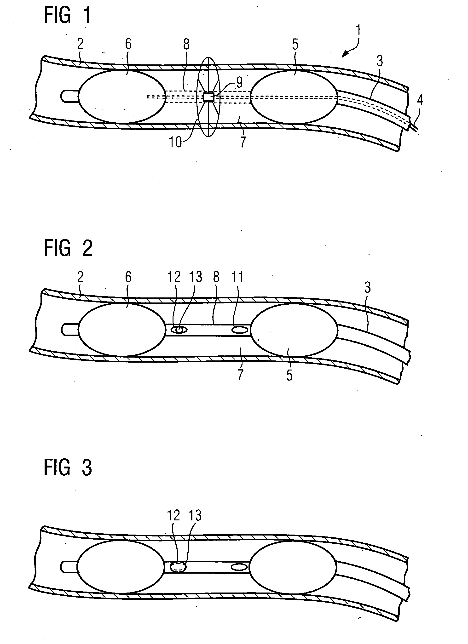
[0026]FIG. 1 shows the inventive catheter device 1 which, in the example shown, is disposed inside a vessel 2. The catheter device 1 consists of a guide catheter 3, which has a lumen, in which an OCT catheter 4 is disposed in a longitudinally displaceable manner. The specific construction of the guide catheter 3 and the various lumina provided will be explained in greater detail below.

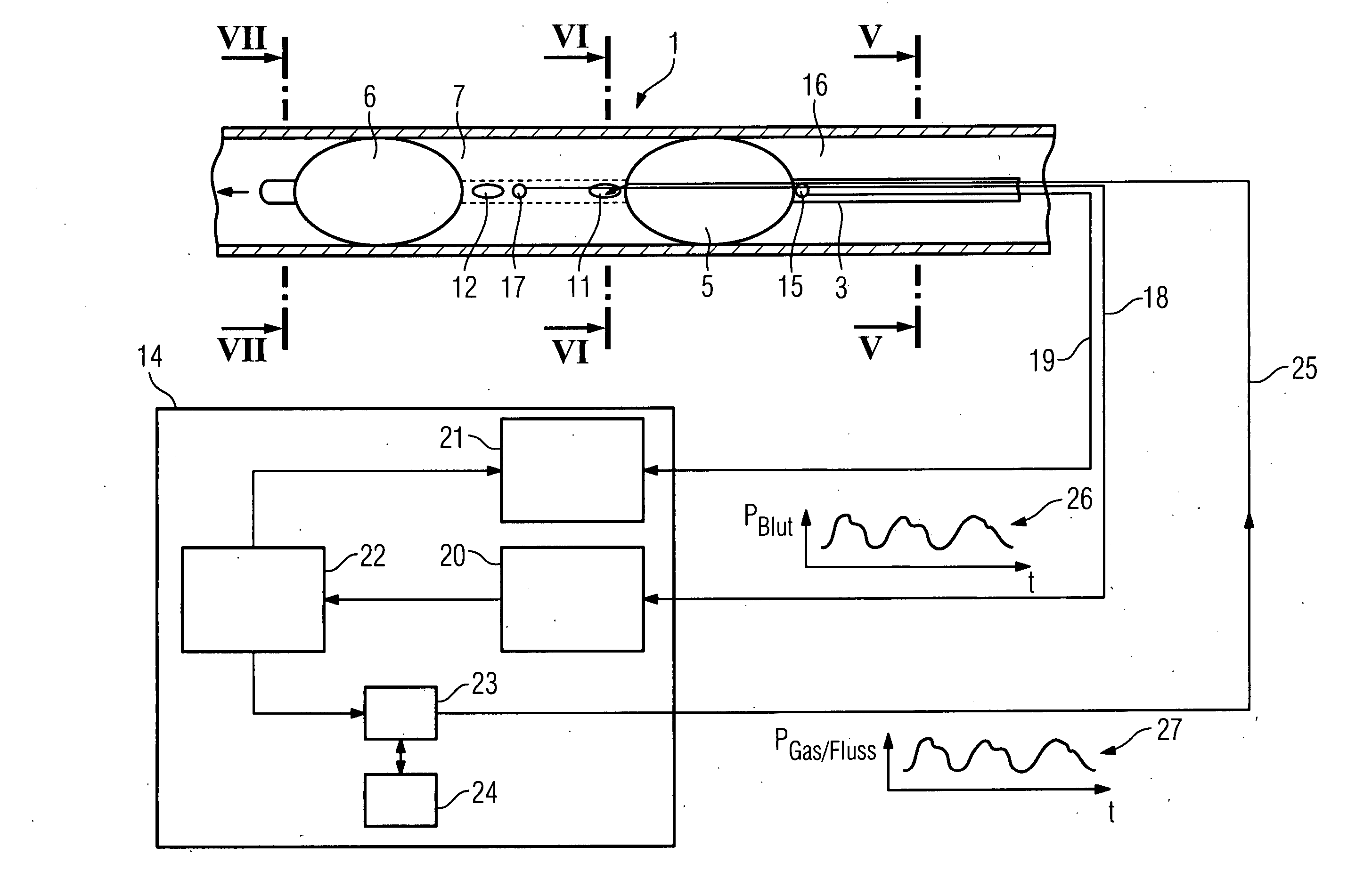
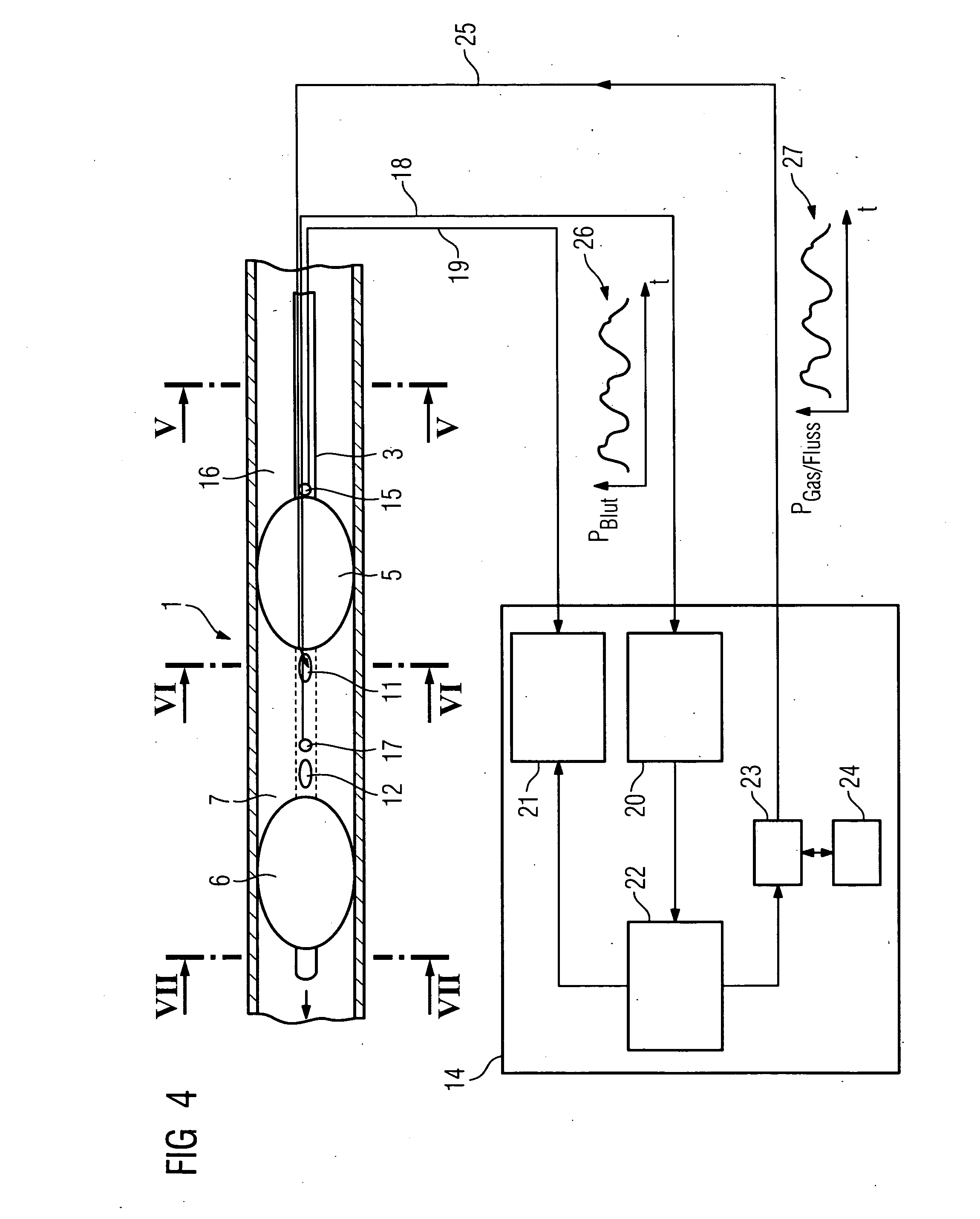
[0027] On the guide catheter 3 there is provided a first reversibly inflatable balloon 5, e.g. made of an elastic plastic material, which can be inflated with an inflation gas via a supply line (not shown in greater detail) from a collapsed shape to the inflated shape shown in FIG. I in which it bears against the vessel wall, sealing it off. Also shown is a second balloon 6 which is likewise inflatable via a supply line (not shown in further detail), which can be a separate supply line or the same supply line as that leading to the balloon 5, from a collapsed position in which it lies close to the gui...


PUM


Abstract

Catheter device for insertion into a vessel of a human or animal body, comprising a guide catheter and, incorporated in same, an OCT catheter with an OCT imaging device, the guide catheter having a balloon inflatable via a supply line for occluding the vessel, as well as a device for delivering a liquid or gas to the vascular region to be recorded by means of the OCT imaging device, in particular the vascular region located distally to the balloon, wherein there is provided on the guide catheter a second inflatable balloon spaced apart from the first balloon for occluding the vessel, wherein the section of the guide catheter between the two balloons is transparent, at least in sections, to the OCT radiation emittable by the OCT imaging device disposed inside the guide catheter.

Description

CROSS REFERENCE TO RELATED APPLICATION [0001] This application claims priority of the German application No. 10 2005 007 574.6 DE filed Feb. 18, 2005, which is incorporated by reference herein in its entirety. FIELD OF THE INVENTION [0002] The invention relates to a catheter device for insertion into a vessel of a human or animal body, comprising a guide catheter and, incorporated in same, an OCT catheter with an OCT imaging device, the guide catheter having a balloon inflatable via a supply line for occluding the vessel, as well as a device for delivering a liquid or gas to the vascular region to be recorded by means of the OCT imaging device, in particular the vascular region located distally to the balloon. BACKGROUND OF THE INVENTION [0003] Optical coherence tomography (OCT) is a light-optical imaging method used in the medical field for, among the things, recording images inside a vessel. For this purpose there is provided an OCT catheter with an OCT imaging device which has at...

Claims


Application Information

Patent Timeline
IPC IPC(8): A61M29/00A61F2/958
CPCA61B5/0066A61B5/0084A61B5/6852A61B5/6853A61M25/003A61M25/1011A61M2025/0036A61M2025/004A61M2025/1052
Inventor CAMUS, ESTELLEKLEEN, MARTINREDEL, THOMAS
Owner SIEMENS HEALTHCARE GMBH
Why Eureka
Try Eureka