
Data encoding apparatus, data encoding method, data output apparatus, data output method, signal processing system, signal processing apparatus, signal processing method, data decoding apparatus, and data decoding method

a data encoding and data technology, applied in the field of apparatus and methods for encoding data, apparatus and methods for outputting data, apparatus and methods for processing signals, and apparatus and methods for decoding data, can solve problems such as significant deterioration of images, illegal copying, and inability to display normal images on display, and achieve good quality

Inactive Publication Date: 2006-08-24
SONY CORP
View PDF19 Cites 46 Cited by
  • Summary
  • Abstract
  • Description
  • Claims
  • Application Information

AI Technical Summary

Benefits of technology

[0039] It is an object of the present invention to disable data to be copied in a condition where its good quality is maintained without deteriorating an output quality owing to the data before being copied.

Problems solved by technology

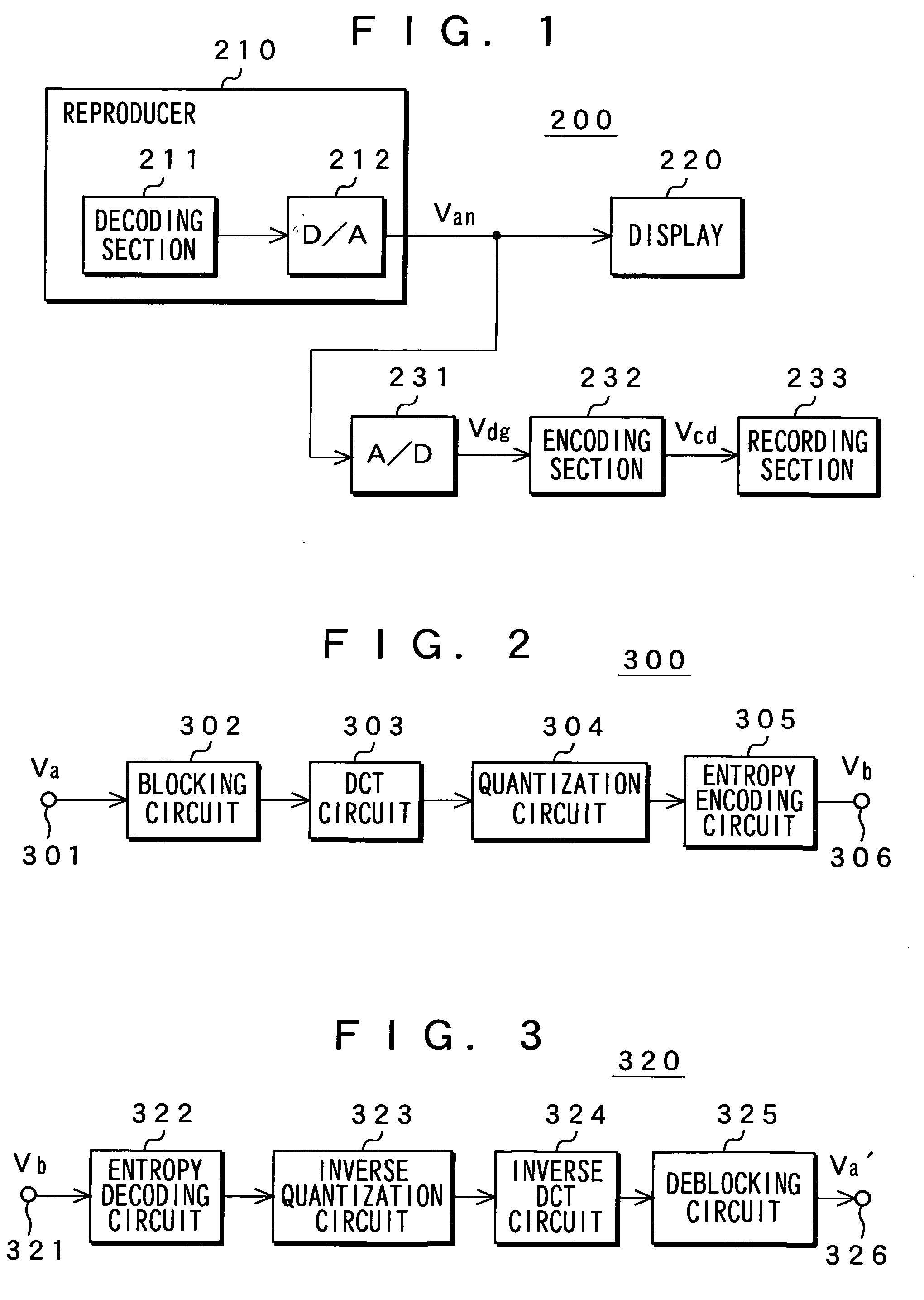
However, there is a danger that illegal copy may be performed by utilizing the analog image data Van output from the reproducer 210 in such an image display system 200.
Although illegal copy can be prevented by outputting the analog image data Van in a condition where it is scrambled or by forbidding it from being output, there may occur a problem that a normal image is not displayed on the display 220.
Hei 10-289522 etc. that by providing a noise information generation section to either one or both of a compression decoding section on the reproduction side and a compression decoding section on the recording side and embedding noise information into digital video data to such an extent that single processing is not enough to identify the information in reproduction of an image, the image may be significantly deteriorated when copy is repeated a plurality of number of times although copy itself is possible, thereby substantially limiting the number of times of performing copy.
If noise information is to be embedded by a compression decoding section on the reproduction side or by a compression encoding section on the recording side, a noise information generation section and a circuit to embed the noise information are required, thus bringing about a problem of an increase in circuit scale.
If encoding and decoding that involve orthogonal transformation is to be performed, on the other hand, quantization and inverse quantization are required, thus deteriorating image data.
However, in this case, the second or later encoding and decoding is accompanied by no remarkable deterioration in a decoded digital image signal, so that it is impossible to prevent the above-described illegal copy by use of the analog image signal Van.

Method used


Image

  • Data encoding apparatus, data encoding method, data output apparatus, data output method, signal processing system, signal processing apparatus, signal processing method, data decoding apparatus, and data decoding method
  • Data encoding apparatus, data encoding method, data output apparatus, data output method, signal processing system, signal processing apparatus, signal processing method, data decoding apparatus, and data decoding method
  • Data encoding apparatus, data encoding method, data output apparatus, data output method, signal processing system, signal processing apparatus, signal processing method, data decoding apparatus, and data decoding method

Examples


first embodiment

[0201] The following will describe the present invention. FIG. 7 shows a configuration of an image display system 1000 according to an embodiment thereof.

[0202] This image display system 1000 has a reproducer 1110 for outputting analog image data Van1 and a display 1120 for displaying an image due to the image data Van1 output from this reproducer 1110.

[0203] The reproducer 1110 decodes, at a decoding section 1111, encoded image data that is reproduced from a recording medium such as an optical disc, not shown, and converts the digital image data thus further decoded and obtained into analog data at a D / A converter 1112, thereby obtaining the analog image data Van1. It is to be noted that the display 1120 may be, for example, a CRT display or an LCD.

[0204] This image display system 1000 further has an encoding apparatus 1130 for performing encoding processing again by utilizing the analog image data Van1 and record the encoded image data on a recording medium such as an optical di...

third embodiment

[0396] It is to be noted that in the above third embodiment, the encoding section 2135 performs block encoding by use of DCT as orthogonal transformation. Orthogonal transformation is not limited to DCT; any other type of orthogonal transformation, for example, discrete sine transform (DST), wavelet transform, etc. may be used. Further, encoding is not limited to block encoding; any other type of encoding may be used. In short, the encoding processing only needs to increase deterioration of the encoded digital signal by utilizing an influence of analog distortion on the digital signal.

[0397] Further, block encoding is not limited to that using orthogonal transformation; any other type of block encoding may be used. For example, adaptive dynamic range coding (ADRC) type of block encoding may be employed.

[0398] In this case, the encoding section 2135 is configured as shown in FIG. 35.

[0399] A digital image signal Vdg1 received at a receiving terminal 2401 is supplied to a blocking c...

fourth embodiment

[0480] Although in the above fourth embodiment, the encoding apparatus 3130 has the recording section 3136 and the display 3139, either one or both of these may be mounted externally to the encoding apparatus 3130.

[0481] Although the above fourth embodiment has handled image data as data, the present invention can be applied similarly to an embodiment for handling audio data. In the case of handling audio data, a display section that serves as display means comes in a speaker that serves as audio output means.

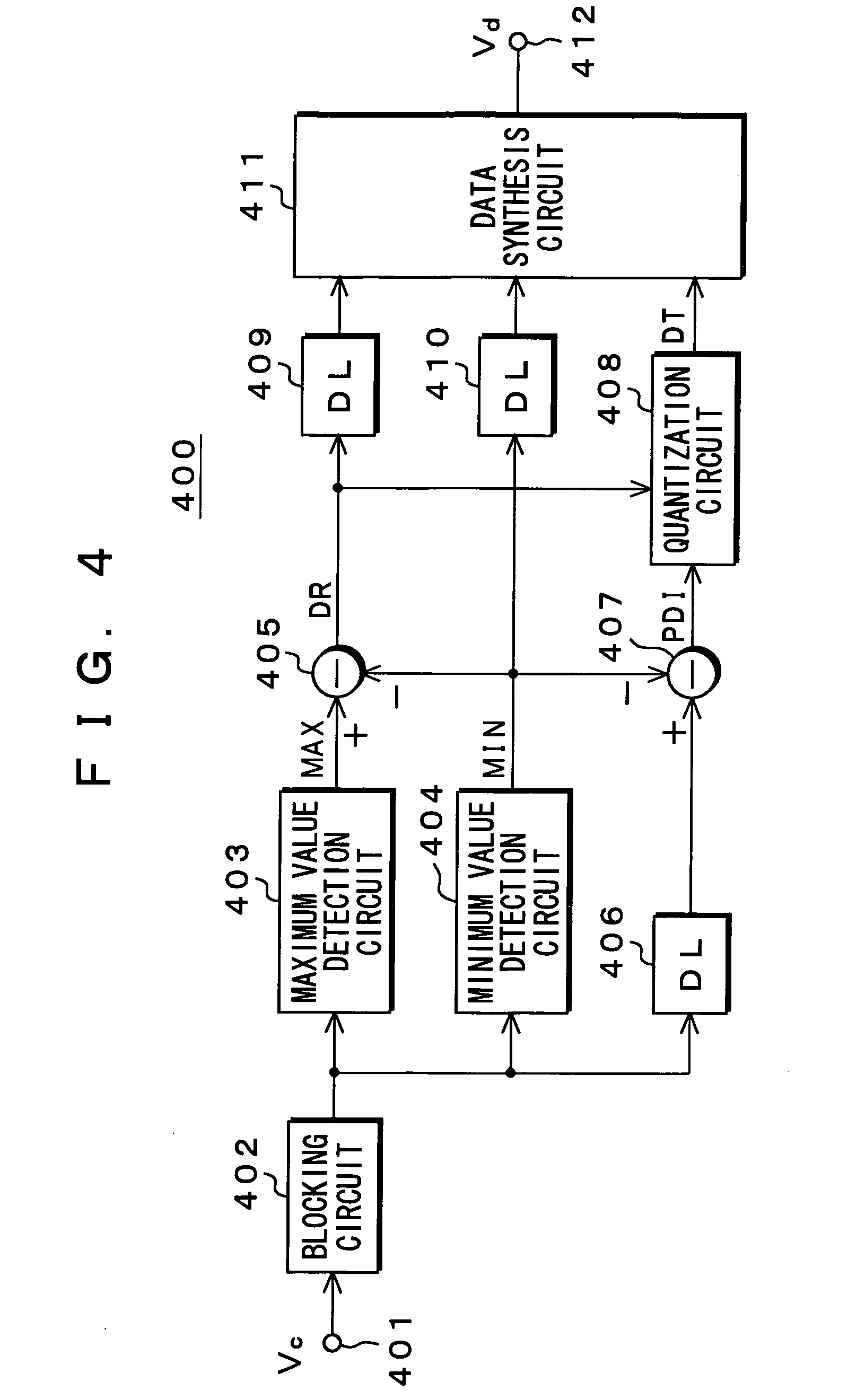
[0482] Although in the above fourth embodiment, the encoding section 3135 in the encoding apparatus 3130 has generated, for each block, block data using, as an added signal, the dynamic range DR and the minimum value MIN as well as an in-block code signal DT, it is of course possible to use, as the added signal, a minimum value NIN and a maximum value MAX additional or a dynamic range DR and a maximum value MAX. In short, it is necessary only to obtain information of the dynam...


PUM


Abstract

This invention relates to an apparatus for encoding data or the like, which disables the data to be copied in a condition where its good quality is maintained without deteriorating a quality of an output owing to the data before being copied. Synchronization signals VD and HD separated from the analog image data Van are delayed and supplied to a clock generation circuit 1133 where a clock CLK is generated in a range of an effective screen based on the synchronization signals. This clock signal CLK is shifted vertically and horizontally so that a phase of image data Vdg1 output from A / D converter 1134 is also shifted. In this image data Vdg1, a signal-deteriorating factor is generated. Encoding section 1135 performs encoding by sampling, conversion encoding, and the like. By shifting the phase of the image data Vdg1, a sampling position and / or a block position are caused to be shifted from a position where obtaining original encoding data relative to the image data Van1, thereby generating significant deterioration in the encoding section 1135.

Description

TECHNICAL FIELD [0001] The present invention relates to an apparatus and a method for encoding data, an apparatus and a method for outputting data, a system, an apparatus, and a method for processing signal, and an apparatus and a method for decoding data. [0002] More specifically, the present invention relates to a data-encoding apparatus etc. for generating a signal-deteriorating factor in received data in accordance with this data or receiving data in which a signal-deteriorating factor is generated to obtain encoded data by encoding the data in which the signal-deteriorating factor is generated so that signal deterioration may be promoted in accordance with the signal-deteriorating factor, thereby disabling data to be copied in a condition where its good quality is maintained without deteriorating an output quality owing to the data before being copied. [0003] The present invention also relates to a data output apparatus etc. for decoding encoded digital data to obtain decoded d...

Claims


Application Information

Patent Timeline
IPC IPC(8): H04N11/04G11B20/00G11B20/10H04N5/913H04N7/26H04N7/50
CPCG11B20/00086G11B20/00818H04N19/98H04N5/913H04N19/61G11B20/10194G11B20/10H04N19/60
Inventor KONDO, TETSUJIRO
Owner SONY CORP
Learn More