Direct digital frequency synthesizer

a digital frequency synthesizer and direct technology, applied in the field of frequency synthesizers, can solve the problems of poor control dynamics, comparatively poor transient recovery performance of fractional-n-methods, and significant increase in phase noise of phase-locking loops, so as to increase the period of pseudo-noise generator noise signals

Active Publication Date: 2006-08-24
ROHDE & SCHWARZ GMBH & CO KG
View PDF10 Cites 8 Cited by
  • Summary
  • Abstract
  • Description
  • Claims
  • Application Information

AI Technical Summary

Benefits of technology

[0023] To generate a white-noise signal, which is as near as possible to the ideal, a noise generator consisting of two parallel-connected pseudo-noise generators with a combinatoria

Problems solved by technology

However, high division factors bring about a significant increase in the phase noise of the phase-locking loop (phase noise of the phase-locking loop=20*log (division factor of the output frequency divider)).
The attenuation of the increased phase noise and/or of the increasing quantization noise by means of low-pass characteristics of the phase-locking loop is purchased at the cost of poorer control dynamics of the phase-locking loop (longer transient recovery time because of reduced bandwidth of the phase-locking loop).
The fractional-N-method also provides a comparatively poor transient recovery performance, because the algorithm of the fractional-N-method approaches the optimum in an integrating manner.
A final disadvantage of the fractional-N-method is that the frequency spectrum of the output frequency contains secondary lines, which occur during the division of the output frequency signal through the fractional-N-frequency divider in the closed-loop branch of the phase-locking loop with a division factor close to a whole-number division factor (so-called “fractional-N-secondary lines”).
The disadvantage with direct digital frequency synthesisers is the occurrence of secondary lines very close to the carrier in

Method used


Image

  • Direct digital frequency synthesizer
  • Direct digital frequency synthesizer
  • Direct digital frequency synthesizer

Examples


Embodiment Construction

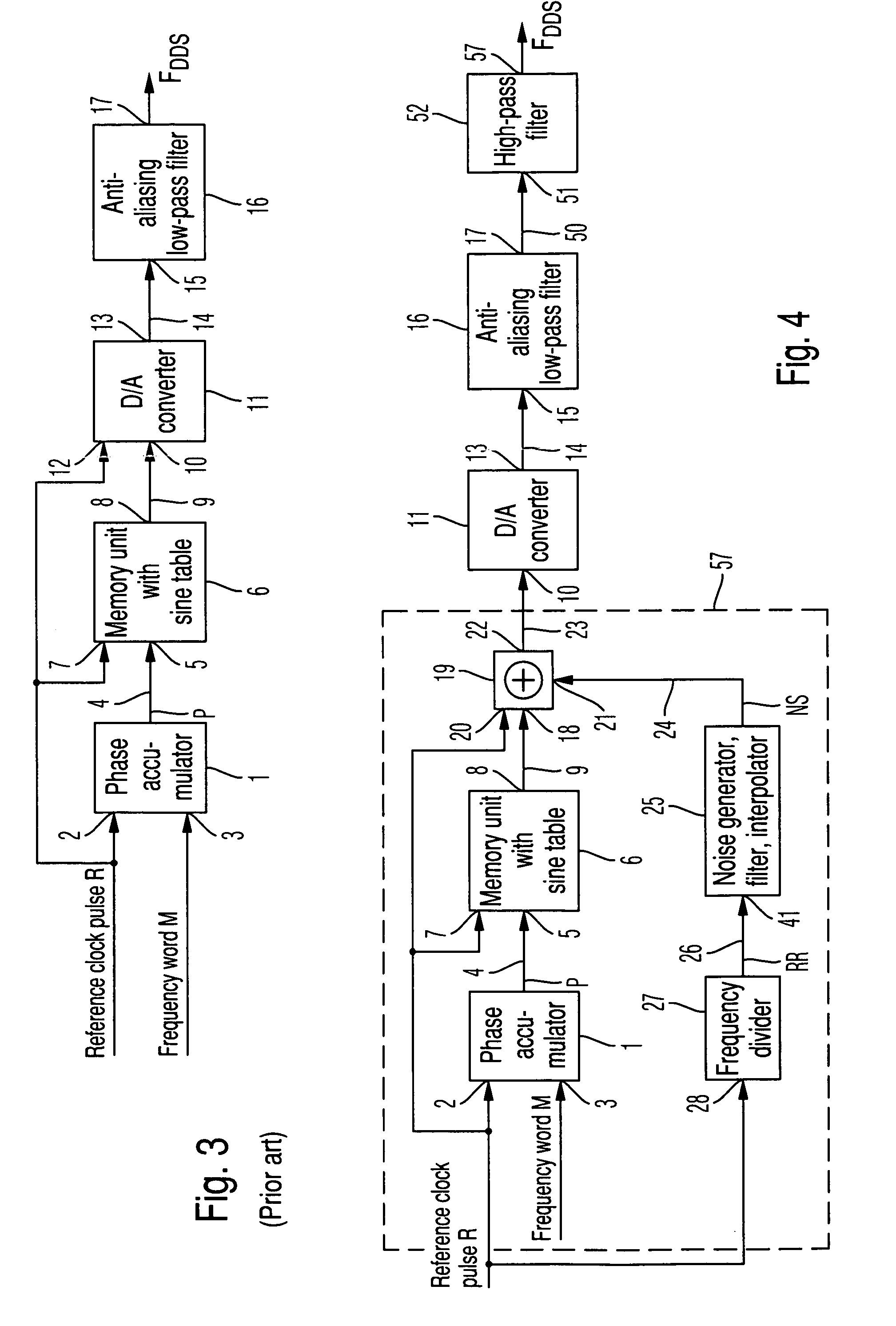
[0038] The direct digital frequency synthesiser according to the invention is described in detail below with reference to an embodiment based on a direct digital frequency synthesiser according to the prior art as shown in FIG. 3 with reference to FIGS. 4, 5, 6 and 11.

[0039] The direct digital frequency synthesiser according to the prior art as shown in FIG. 3 comprises a phase accumulator 1, which is timed at its first input 2 with a reference clock pulse R. At the reference clock pulse R, the phase accumulator 1 increments its internal counter by one phase increment, which is specified in the frequency word M and supplied to it via its second input 3. The maximum level of the internal counter is determined by its bit number NB and has the value 2NB−1. When the maximum level 2NB−1 of the internal counter is reached through the process of phase incrementation, the internal counter starts to increment from the beginning again and a cyclical incrementation process is continued with t...


PUM


Abstract

A frequency synthesiser according to the direct digital synthesis method is provided. The frequency synthesiser includes a phase accumulator for the cyclical incrementation of a phase signal by a phase increment M present at the input of the phase accumulator, a memory unit with a table of sine-function values stored in its memory cells for the determination of sine-function values corresponding to phase values of the phase signal, a digital-to-analog converter for the conversion of time-discrete sine-function values into a quasi-analog sinusoidal time function and an anti-aliasing low-pass filter for smoothing the quasi-analog sinusoidal time function. The frequency synthesiser additionally contains an adder, which is connected between the memory unit and the digital-to-analog converter and which superimposes a non-periodic signal over the time-discrete sine-function values.

Description

BACKGROUND OF THE INVENTION [0001] 1. Field of the Invention [0002] The invention relates to a frequency synthesiser according to the direct digital synthesis method with the capability of suppressing secondary lines in the frequency spectrum of the output frequency signal. [0003] 2. Description of the Background Art [0004] Contemporary high-resolution broadband frequency synthesisers are essentially based upon two different methods, the fractional-N-method and the direct digital synthesis method. [0005] In the case of the fractional-N-method, the frequency is adjusted through defined frequency division of the reference frequency in a forward branch disposed upstream of the phase-locking loop or of the output frequency of the phase-locking loop in the closed-loop branch of the phase-locking loop, in each case via one programmable frequency divider. The frequency divider operates digitally via sigma-delta modulation of a digital word acting as a reference frequency value. A high-freq...

Claims


Application Information

Patent Timeline
IPC IPC(8): H03B21/00G06F1/03H03L7/18H03L7/185
CPCG06F1/0328H03L7/18H03L7/185
Inventor KLAGE, GUNTHER
Owner ROHDE & SCHWARZ GMBH & CO KG
Why Eureka
Try Eureka