
Wave solder nozzle

a soldering nozzle and wave technology, applied in the direction of welding/cutting media/materials, manufacturing tools, soldering apparatus, etc., can solve the problems of increased solder dross production, inaccurate soldering applications, and difficulty in controlling the velocity of solder material generated by the backside of the wave, so as to improve the flow of solder material

Inactive Publication Date: 2006-08-24
SPEEDLINE TECH
View PDF7 Cites 19 Cited by
  • Summary
  • Abstract
  • Description
  • Claims
  • Application Information

AI Technical Summary

Benefits of technology

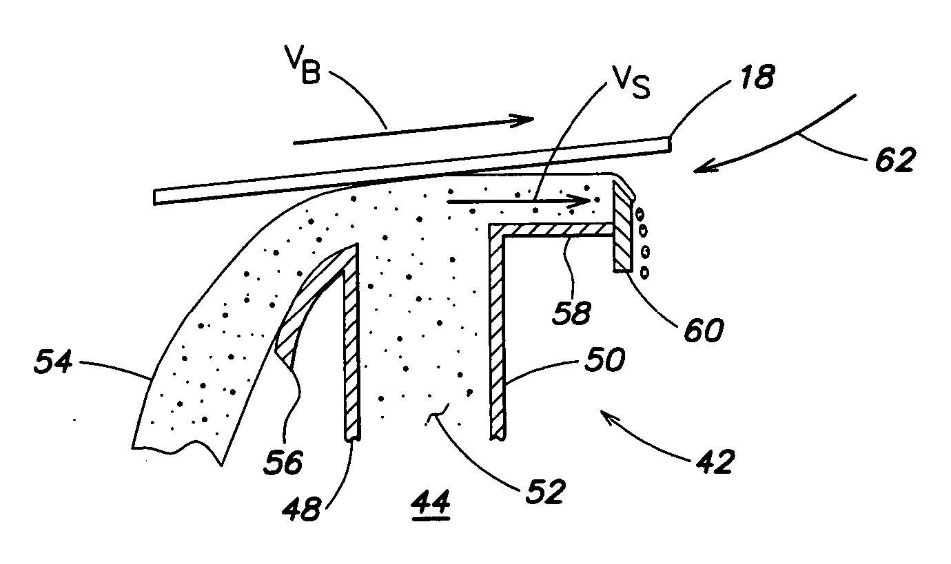
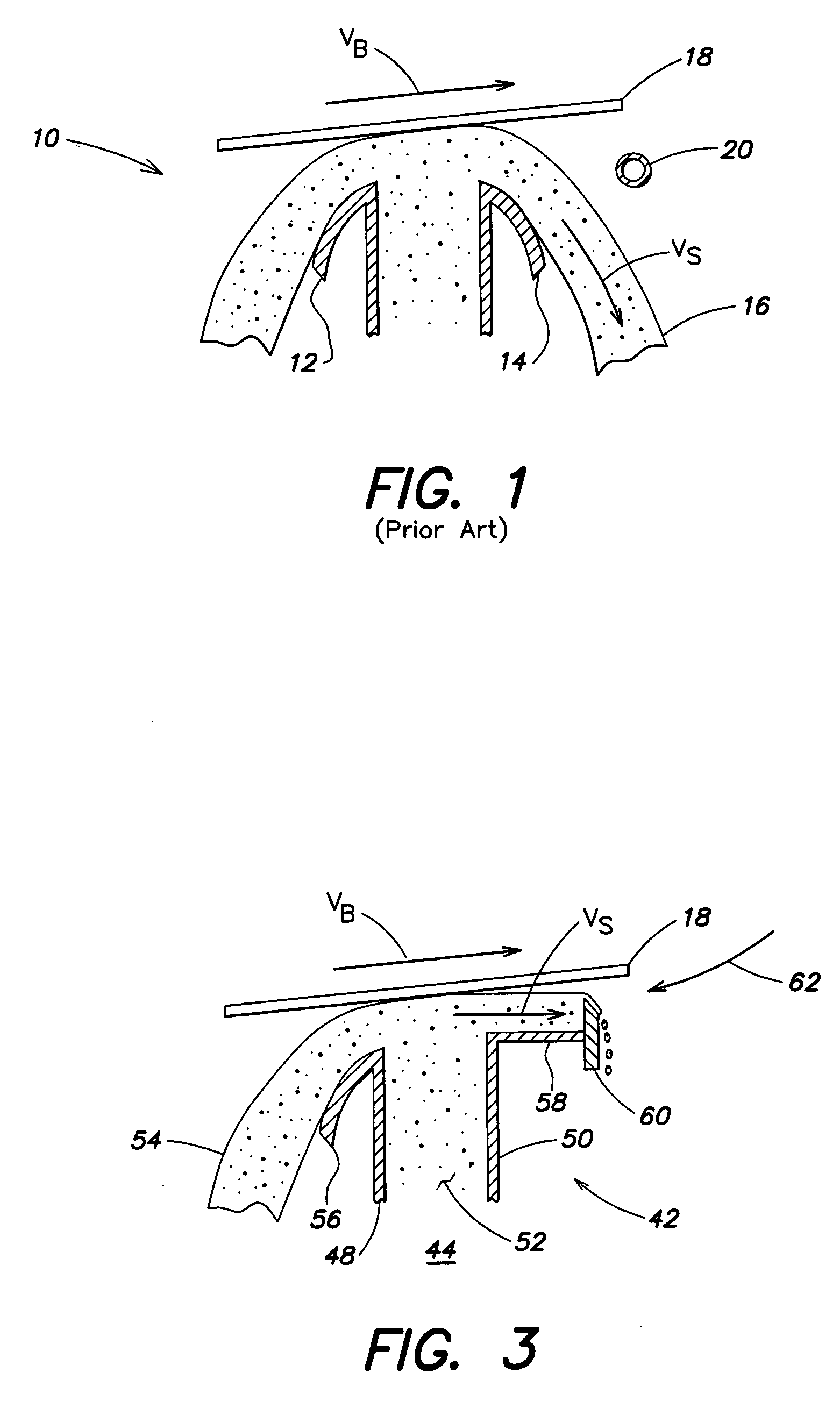
[0009] A first aspect of the invention is directed to a wave solder nozzle adapted to deliver solder material to perform a wave soldering operation on a printed circuit board in an inert atmosphere. The wave solder nozzle comprises a front plate and a back plate coupled to the front plate. The front plate and the back plate define a channel through which solder material flows. The nozzle further comprises an exit trough extending from the back plate. The exit trough has a weir provided at one end of the exit trough. The exit trough is constructed and arranged to control the flow of solder material from the wave solder nozzle. A surface of the exit trough is wettable to improve the flow of solder material out of the wave solder nozzle.
[0013] A third aspect of the invention is directed to a method of improving the flow of solder material out of a wave solder nozzle of a wave soldering machine in an inert atmosphere. The method comprises: delivering solder material to a wave solder nozzle; performing a wave soldering operation on a printed circuit board; and improving the flow of solder material over the wave solder nozzle by providing a surface of the wave solder nozzle with a wettable material.

Problems solved by technology

Inconsistency of flow of solder material may cause inaccurate soldering applications.
One disadvantage with the inert solder wave nozzle 10 is that it is difficult to control the velocity of solder material being generated from the backside of the wave.
The difference in the velocities of the PCB and solder wave results in a phenomenon called “bridging,” which is the undesirable interconnection of solder material between adjacent metallic pads of the PCB.
One disadvantage with known air nozzle designs is increased solder dross production.

Method used


Image

  • Wave solder nozzle
  • Wave solder nozzle
  • Wave solder nozzle

Examples


Embodiment Construction

[0020] This invention is not limited in its application to the details of construction and the arrangement of components set forth in the following description or illustrated in the drawings. The invention is capable of other embodiments and of being practiced or of being carried out in various ways. Also, the phraseology and terminology used herein is for the purpose of description and should not be regarded as limiting. The use of “including,”“comprising,”“having,”“containing,”“involving,” and variations thereof herein, is meant to encompass the items listed thereafter and equivalents thereof as well as additional items.

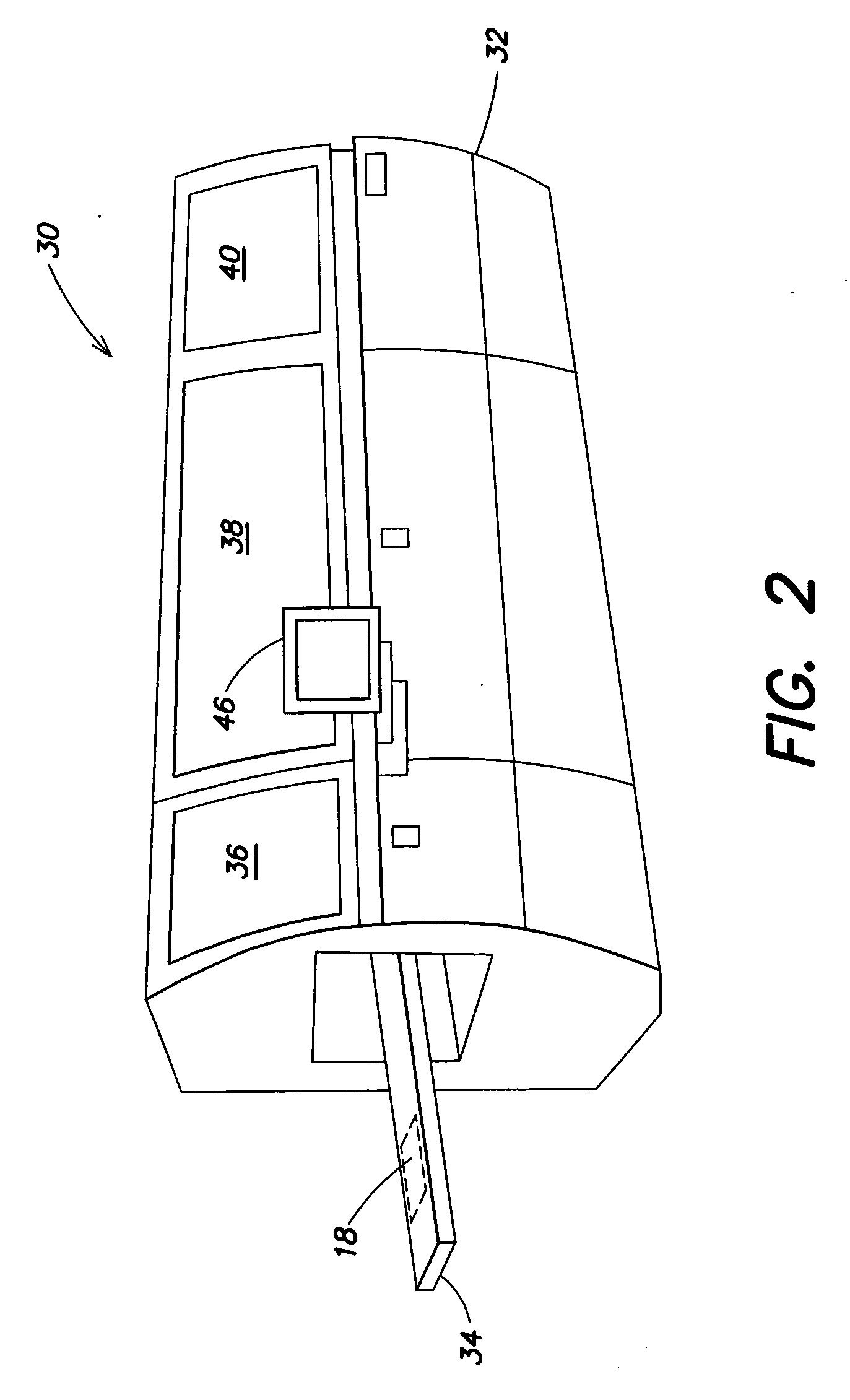
[0021] For purposes of illustration, and with reference to FIG. 2, embodiments of the present invention will now be described with reference to a wave soldering machine, generally indicated at 30, used to perform a solder application on a printed circuit board 18. The wave soldering machine 30 is one of several machines in a PCB fabrication / assembly line. As shown...


PUM

PropertyMeasurementUnit
angleaaaaaaaaaa
wettableaaaaaaaaaa
velocityaaaaaaaaaa

Abstract

A wave solder nozzle is capable of delivering solder material to perform a wave soldering operation on a printed circuit board in an inert atmosphere. The wave solder nozzle includes a front plate and a back plate coupled to the front plate. The front plate and the back plate define a channel through which solder material flows. The nozzle further includes an exit trough extending from the back plate. The exit trough has a weir provided at one end of the exit trough. The exit trough is constructed and arranged to control the flow of solder material from the wave solder nozzle. A surface of the exit trough is wettable to improve the flow of solder material out of the wave solder nozzle. A method of improving the flow of solder material through the nozzle is also disclosed.

Description

BACKGROUND OF INVENTION [0001] 1. Field of Invention [0002] The present invention relates generally to apparatus for manufacturing printed circuit boards and for assisting the process of soldering metals to integrated circuit boards, and more particularly to a wave soldering machine having an improved wave solder nozzle adapted to better control the flow of solder when performing a solder application on a printed circuit board. [0003] 2. Discussion of Related Art [0004] Generally speaking, in a wave soldering machine, a printed circuit board (PCB) is moved by a conveyor on an inclined path past a fluxing station, a preheating station, and finally a wave soldering station. At the wave soldering station, a wave of solder is caused to well upwardly (by means of a pump) through a wave solder nozzle and contact portions of the PCB to be soldered. The efficiency of the soldering process is affected by a number of concerns, one of which is the ability to control the flow of solder material...

Claims


Application Information

Patent Timeline
Patent Type & Authority Applications(United States)
IPC IPC(8): B23K31/02
CPCB23K1/0016B23K1/085B23K3/0653B23K2201/42H05K3/3468B23K2101/42
Inventor MORRIS, JAMES M.
Owner SPEEDLINE TECH
Learn More