
Image processing system, projector, and image processing method

a technology of image processing and projector, applied in the field of image processing system, projector, image processing method, can solve the problems of not being able to properly reduce the environmental influence of the projection image after distortion correction, and the time taken by the related-art projector,

Inactive Publication Date: 2006-08-17
SEIKO EPSON CORP
View PDF5 Cites 38 Cited by
  • Summary
  • Abstract
  • Description
  • Claims
  • Application Information

AI Technical Summary

Benefits of technology

The invention relates to an image processing system that can sense and correct distortion of a projection image caused by environmental factors. The system includes an image distortion sensing section, an environmental influence sensing section, a projection area information generation section, an image distortion correction section, a display area information generation section, an environmental influence reduction section, and a projection section. The system can also generate a specific differential image based on the image distortion sensing information and the environmental influence sensing information. The technical effects of the invention include improved image quality and reduced environmental influence on the projection image.

Problems solved by technology

Therefore, a related-art projector takes time for the projection image distortion correction processing and the environmental influence reduction processing.
However, when distortion of the projection image has been corrected, the projection image may not be displayed in the area in which the projection image is originally displayed due to distortion correction.
In this case, even if the environmental influence reduction processing is performed by using the sensing information of that area, the environmental influence may not be appropriately reduced from the projection image after distortion correction.
However, since the projector disclosed in JP-A-2004-48694 does not take into consideration the position and the shape of the projection image after distortion correction, the environmental influence may not be appropriately reduced.

Method used


Image

  • Image processing system, projector, and image processing method
  • Image processing system, projector, and image processing method
  • Image processing system, projector, and image processing method

Examples


first embodiment

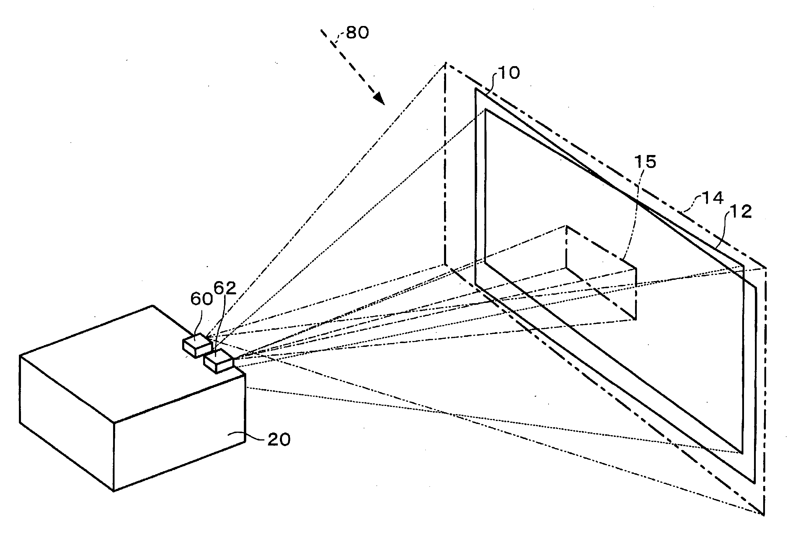
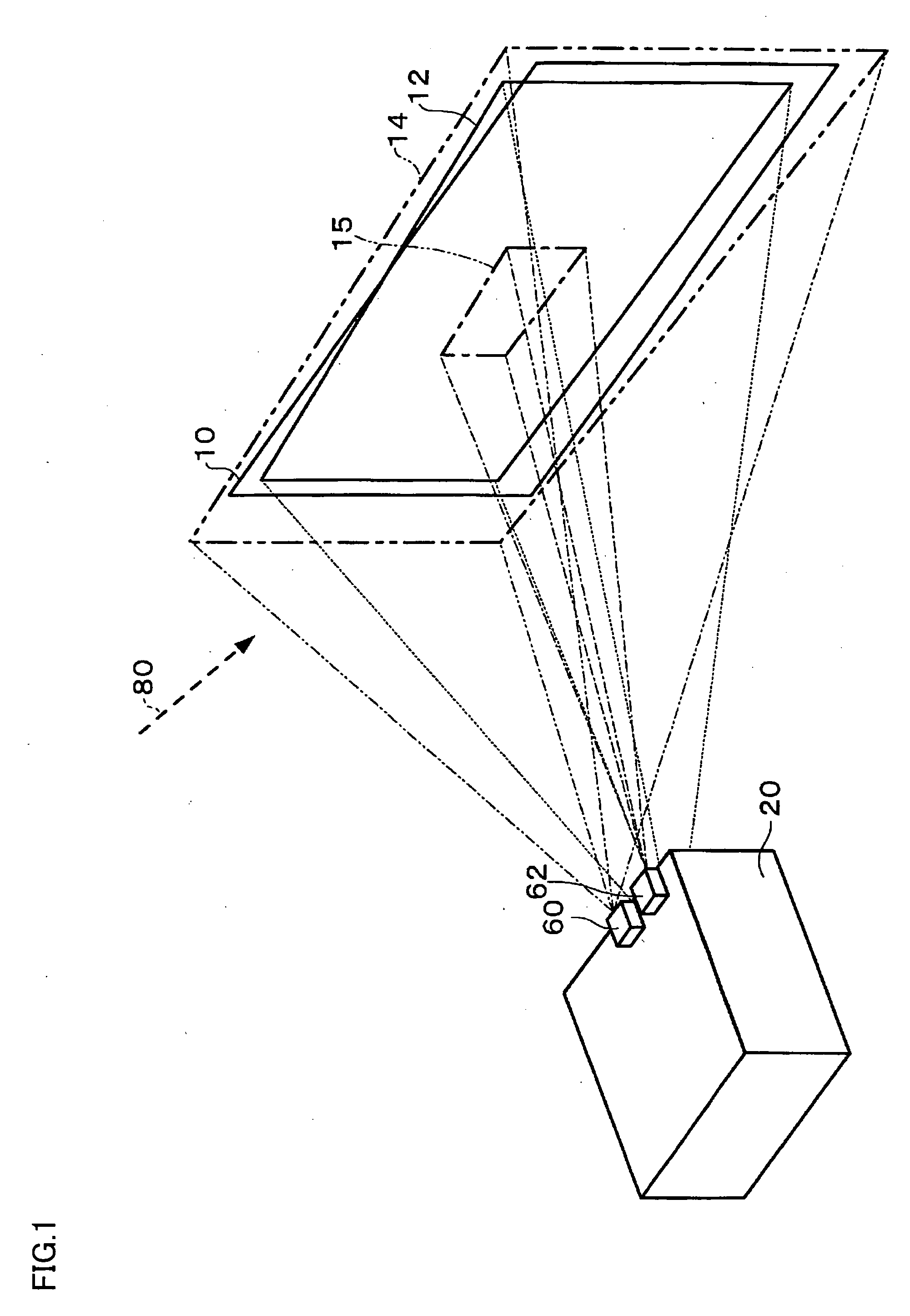
[0145]FIG. 1 is a schematic diagram showing an image projection state according to the first embodiment.

[0146] A projector 20 projects an image onto a screen 10 having a projection target area. As a result, a projection image 12 is displayed on the screen 10.

[0147] In the first embodiment, a part of the screen 10 is influenced by external light 80 (environmental influence), as shown in FIG. 1. Since the projector 20 obliquely projects an image onto the screen 10, the projected image 12 is distorted so that keystone distortion occurs. As shown in FIG. 1, a part of the projection image 12 is positioned outside the screen 10.

[0148] In the first embodiment, the projector 20 includes an image distortion sensor 60 for correcting distortion of the projection image 12, and an environmental influence sensor 62 for reducing environmental influence. The image distortion sensor 60 senses an image distortion sensing area 14 including the projection image 12 projected onto the screen 10 (may b...

second embodiment

[0215] When using a line sensor, a phase difference sensor, or the like as the image distortion sensing section 180, or when causing the image distortion correction section 103 to detect the peak position of the brightness index value (e.g. luminance value or illuminance value) included in the image distortion sensing information and correct distortion of the projection image 12 based on the peak position, the projector 20 need not use the projection target area information and the projection area information. When the zoom section 194 is not controlled by using the control section 107, the projector 20 need not use the display area information.

[0216] A second embodiment, in which the projector 20 performs the environmental influence reduction processing and the image distortion correction processing without using the projection target area information, the projection area information, and the display area information, is described below.

[0217]FIG. 7 is a flowchart showing the flo...


PUM


Abstract

A projector includes an image distortion sensing section which generates image distortion sensing information, an environmental influence sensing section which generates environmental influence sensing information, a projection area information generation section which generates projection area information, an image distortion correction section which corrects distortion of a projection image and generates correction information indicating the degree of correction, a display area information generation section which generates display area information indicating the display area of the projection image after distortion correction based on the projection area information and the correction information, an environmental influence reduction section which performs processing of reducing environmental influence, a projection section which projects the projection image, and a differential image generation section which generates a differential image.

Description

[0001] Japanese Patent Application No. 2005-36172, filed on Feb. 14, 2005, is hereby incorporated by reference in its entirety. BACKGROUND OF THE INVENTION [0002] The present invention relates to an image processing system which performs projection image distortion correction processing and environmental influence reduction processing, a projector, and an image processing method. [0003] In recent years, a projector has been proposed which corrects distortion of a projection image and reduces environmental influence (e.g. influence of external light or influence of screen color) by projecting an image onto a screen using a projector including a sensor, sensing the projected image using the sensor, and performing image processing. [0004] A related-art projector separately performs the projection image distortion correction processing and the environmental influence reduction processing. Therefore, a related-art projector takes time for the projection image distortion correction proces...

Claims


Application Information

Patent Timeline
Patent Type & Authority Applications(United States)
IPC IPC(8): G03B21/14
CPCG03B21/14H04N9/3182H04N9/3185H04N9/3194H04N9/3197
Inventor MATSUDA, HIDEKI
Owner SEIKO EPSON CORP
Learn More