
Phase shifting waveguide and module utilizing the waveguides for beam phase shifting and steering

a phase shifting waveguide and waveguide technology, applied in the direction of delay lines, electrical equipment, antennas, etc., can solve the problems of inability to accurately adjust the phase shift and steering angle, the use of these devices becomes impractical, and the cost is too small and expensiv

Inactive Publication Date: 2006-08-17
TELEDYNE LICENSING
View PDF6 Cites 4 Cited by
  • Summary
  • Abstract
  • Description
  • Claims
  • Application Information

AI Technical Summary

Benefits of technology

The waveguide structure increases the signal's propagation constant, shifts its phase, and enables efficient amplification and beam steering with reduced signal degradation, making it suitable for high-frequency applications.

Problems solved by technology

As the signal frequencies continue to increase, a point is reached where use of these devices becomes impractical.
They become too small and expensive, require precision machining to produce, and their insertion loss can become too great.
However, commercial use of these “open” systems is not practical because they are fragile and can be contaminated by the surrounding environment.
Also, there is no simple, durable and reliable mechanism for beam phase shifting or steering.
In addition to their size and insertion loss disadvantages they do not provide an optimal signal to drive an amplifier array.
The array's edge amplifiers become ineffective, significantly reducing the array's potential output power.

Method used


Image

  • Phase shifting waveguide and module utilizing the waveguides for beam phase shifting and steering
  • Phase shifting waveguide and module utilizing the waveguides for beam phase shifting and steering
  • Phase shifting waveguide and module utilizing the waveguides for beam phase shifting and steering

Examples


Embodiment Construction

Waveguide Phase Shifter

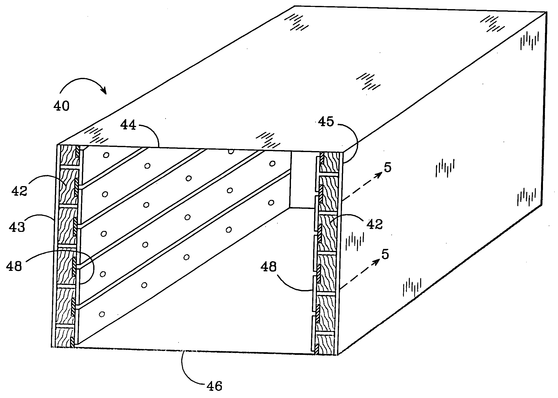
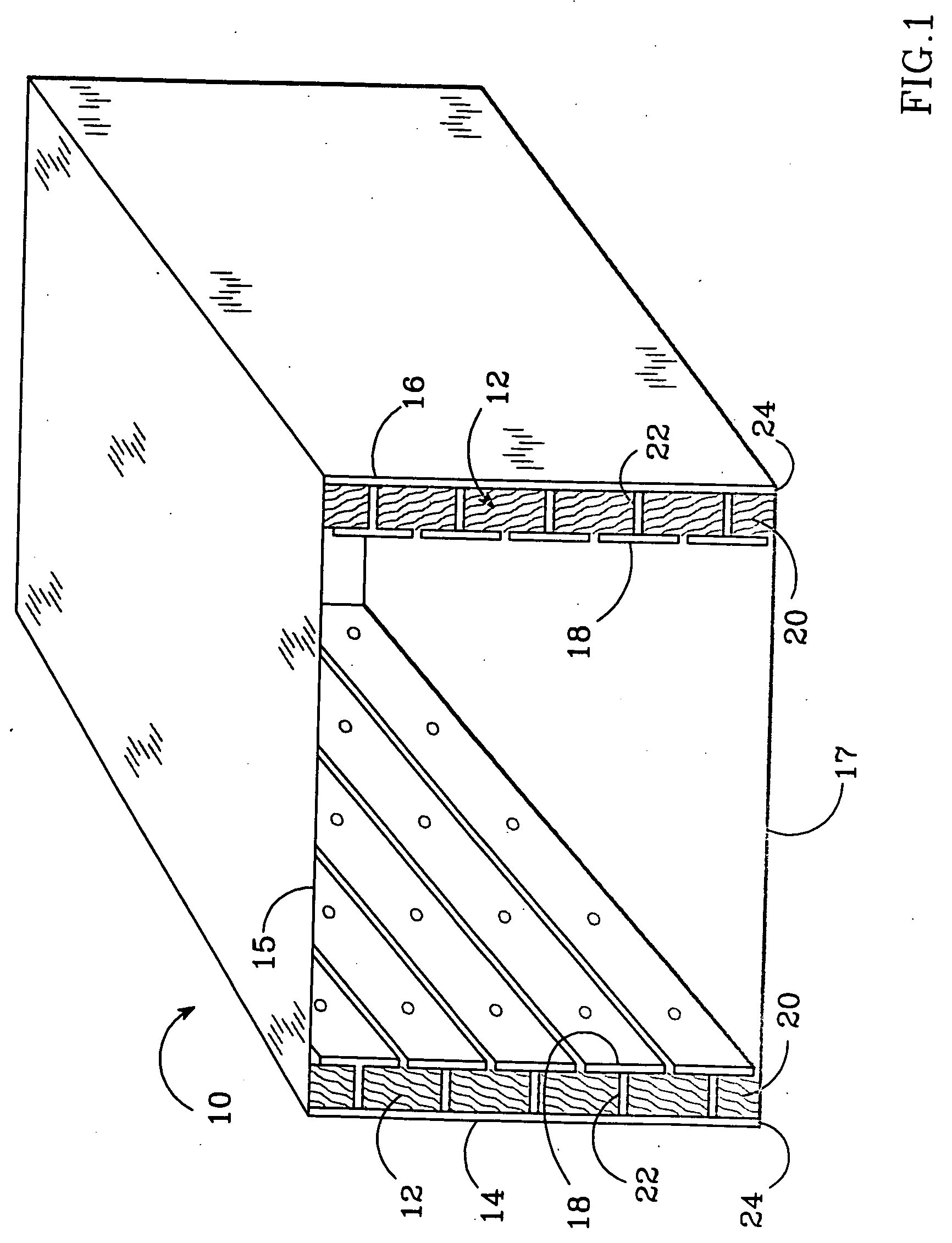
[0035]FIG. 1 shows a new phase shifting waveguide 10 constructed in accordance with the present invention, which comprises a top wall 15, bottom wall 17, and left and right sidewalls 14, 16. It further comprises strip impedance structures 12 on its left and right sidewalls 14, 16. Each impedance structure includes a plurality of conductive strips 18 parallel to the waveguide's longitudinal axis and facing its interior. The strips 18 are made of a conductive material and are provided on a substrate of dielectric material 20. Conductive sheets 24 are provided over the exterior of each dielectric substrate 20 with vias 22 included along each strip's longitudinal axis extending through the substrate to its respective sheet 24 to form a conductive path between the strips and the sheets.

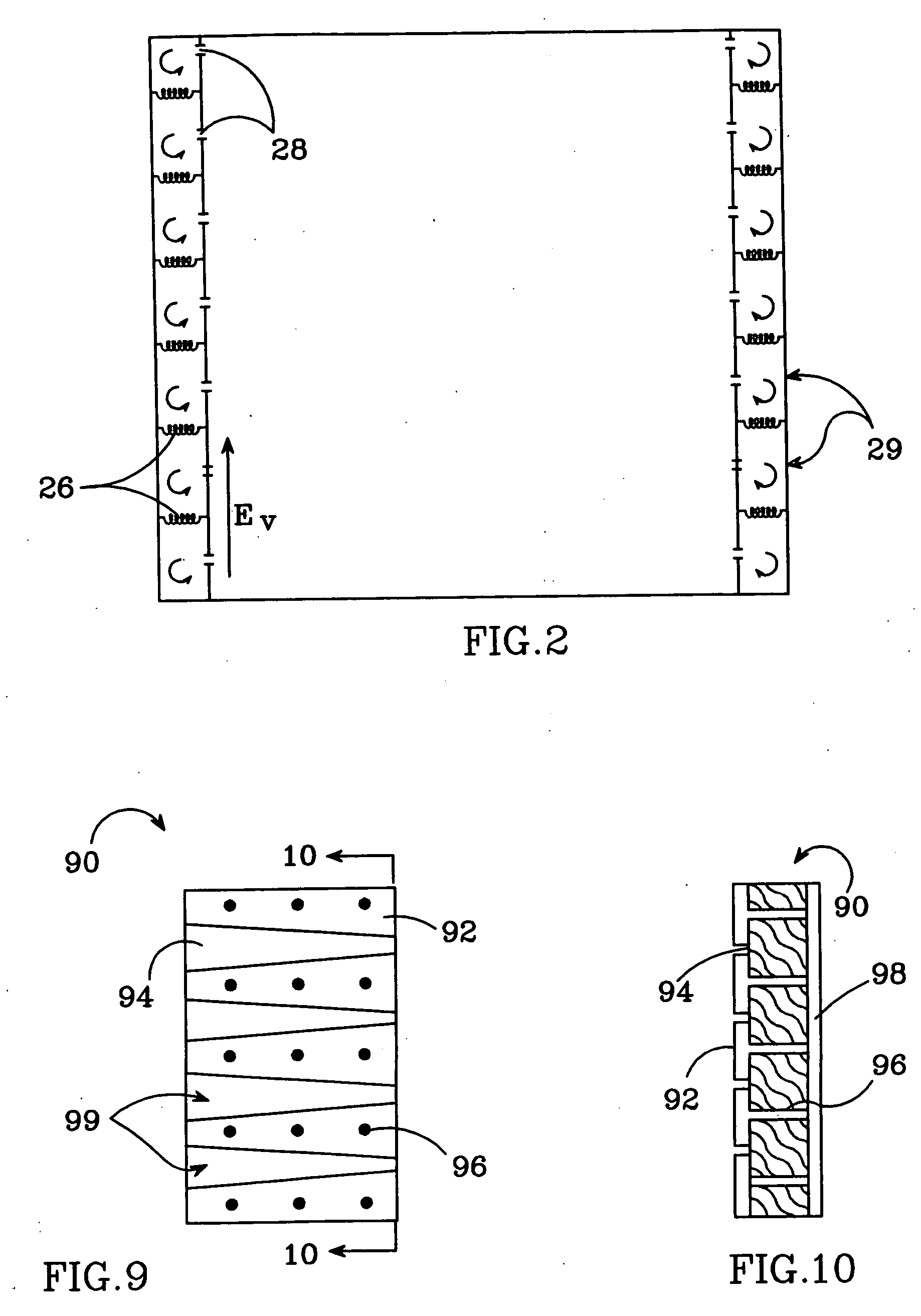
[0036] With the impedance structures 12 on its sidewalls, the waveguide 10 is particularly applicable to passing vertically polarized signals that have an E field transverse to th...


PUM


Abstract

A waveguide is disclosed that shifts the phase of the signal passing through it. In one embodiment, the waveguide has an impedance structure on its walls that resonates at a frequency lower than the frequency of the signal passing through the waveguide. This causes the structure to present a capacitive impedance to the signal, increasing its propagation constant and shifting its phase. Another embodiment of the new waveguide has impedance structures on its wall that are voltage controlled to change the frequency at which the impedance structures resonate. The range of frequencies at which the structure can resonate is below the frequency of the signal passing through the waveguide. This allows the waveguide cause a adjust the shift in the phase of its signal. An amplifier array can be included in the waveguides to amplify the signal. A module can be constructed of the new waveguides and placed in the path of a millimeter beam. A portion of the beam passes through the waveguides and the beam can be shifted or steered depending on the phase shift through each waveguide.

Description

BACKGROUND OF THE INVENTION [0001] 1. Field of the Invention [0002] This invention relates to phase shifting and steering of high frequency electromagnetic signals. [0003] Description of the Related Art [0004] Electromagnetic signals are commonly guided from a radiating element to a destination via a coaxial cable, metal waveguide, or microstrip transmission line. As the frequency of the signal increases, these devices must have smaller cross-sections to transmit the signals. For example, a metal waveguide that is 58.420 cm wide and 29.210 high at its inside dimensions, transmits signals in the range of 0.32 to 0.49 GHz. A metal waveguide that is 0.711 cm wide and 0.356 cm high at its inside dimensions, transmits signals in the range of 26.40 to 40.00 GHz. [Dorf, The Electrical Engineering Handbook, Second Edition, Section 37.2, Page 946 (1997)]. As the signal frequencies continue to increase, a point is reached where use of these devices becomes impractical. They become too small a...

Claims


Application Information

Patent Timeline
Patent Type & Authority Applications(United States)
IPC IPC(8): H01P1/18H01P1/185H01Q15/04
CPCH01P1/182H01P1/185H01Q3/46H01Q15/04
Inventor HIGGINS, JOHN A.
Owner TELEDYNE LICENSING
Learn More