
Stress-relieved diamond inserts

a diamond insert and stress-relief technology, applied in the field of cutting elements, can solve the problems of insert breakage or delamination of inserts under drilling conditions, dissimilar materials being bonded to each other, and cutting elements of tungsten carbide tend to fail due to excessive wear and tear

Inactive Publication Date: 2006-08-17
SMITH INT INC
View PDF6 Cites 75 Cited by
  • Summary
  • Abstract
  • Description
  • Claims
  • Application Information

AI Technical Summary

Benefits of technology

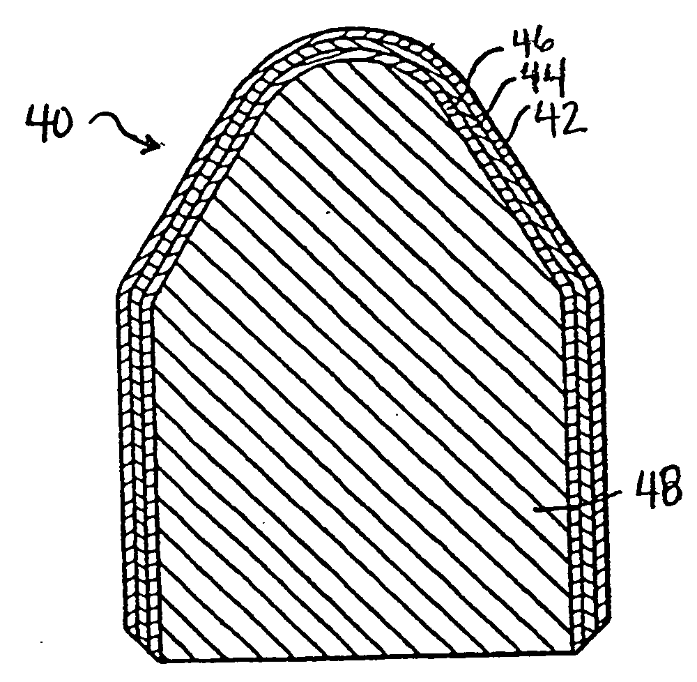
The present invention is about a drill bit with a cutting element that has reduced stress. The cutting element includes a substrate, a transition layer, and a polycrystalline diamond layer. The cutting element is made by a method that involves subjecting it to a heat treatment process. The technical effect of this invention is that the drill bit has better performance and durability due to the reduced stress on the cutting element.

Problems solved by technology

Tungsten carbide cutting elements tend to fail by excessive wear because of their relative softness in comparison to ultrahard materials such as diamond.
The HP / HT conditions used to manufacture the cutting elements result in dissimilar materials being bonded to each other.
The residual stress induced on the diamond layer and substrate can often result in insert breakage or delamination under drilling conditions.
However, this study examined only effects of changes to the design of the PCD and transition layers to lower residual stress, it did not consider the effects of processing.

Method used


Image

  • Stress-relieved diamond inserts
  • Stress-relieved diamond inserts
  • Stress-relieved diamond inserts

Examples


example

[0050] One way to assess the residual stress of a cutting element is by utilizing Raman spectroscopy. A schematic of a configuration for such tests is shown in FIG. 6. Laser probe 62 is directed at the apex of the polycrystalline diamond dome 64 of cutting element 60. Diamond has a single Raman-active peak, which under stress free conditions is located at ω0=1332.5 cm−1. For polycrystalline diamond, this peak is shifted with applied stress according to the relation: Δ⁢ ⁢ω=ω0⁢γB⁢σH

where Δω is the shift in the Raman frequency, γ is the Grunesian constant, equaling 1.06, B is the bulk modulus, equaling 442 GPa, and σH is the hydrostatic stress. σH is defined as: σH=σ1+σ2+σ33

where σ1, σ2, and σ3 are the three orthogonal stresses in an arbitrary coordinate system, the sum of which equals the first stress invariant. In the center of the apex of an insert, it is reasonable to assume equibiaxial conditions (σ1=σ2=σB and σ3=0). In which case, the relation between the biaxial stress σB an...


PUM

PropertyMeasurementUnit
thicknessaaaaaaaaaa
thicknessaaaaaaaaaa
thicknessaaaaaaaaaa

Abstract

A drill bit including at least one stress-relieved cutting element, wherein the at least one cutting element is mounted on the drill bit, wherein the stress-relieved cutting element includes a substrate, at least one transition layer disposed upon the substrate and a polycrystalline diamond layer having a thickness of at least 0.008 inches disposed upon the at least one transition layer.

Description

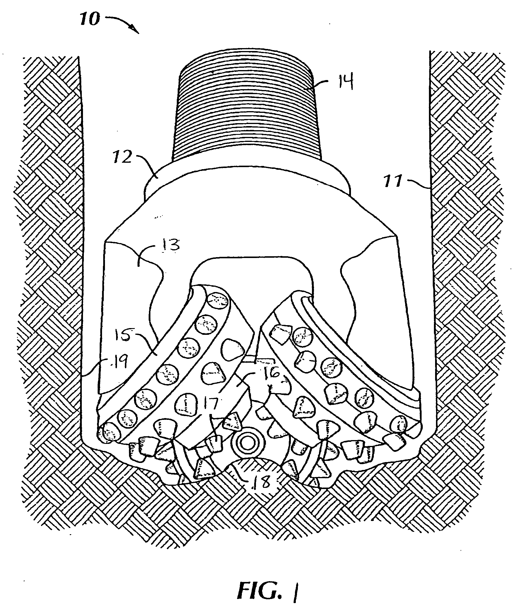
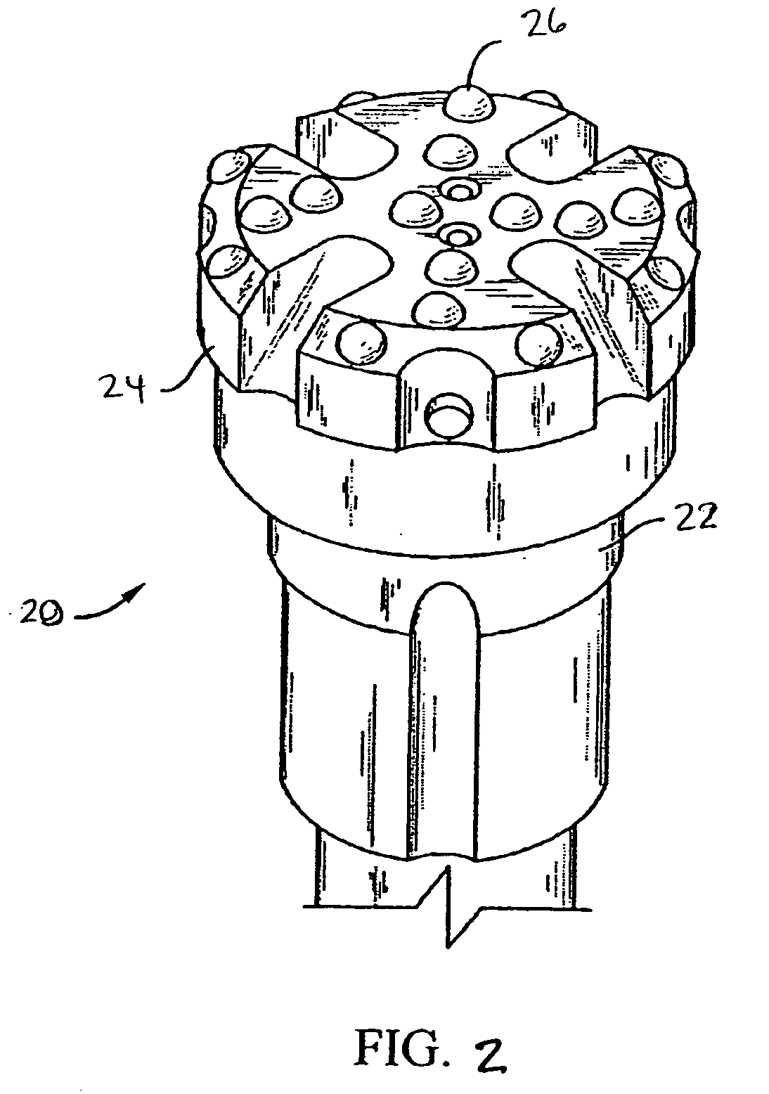
CROSS-REFERENCE TO RELATED APPLICATIONS [0001] This application claims priority, pursuant to §119(e), of U.S. Provisional Ser. No. 60 / 653,256 filed on Feb. 15, 2005, which is herein incorporated by reference in its entirety.BACKGROUND OF INVENTION [0002] 1. Field of the Invention [0003] The invention relates generally to cutting elements used on rock bits such as roller cone rock bits, hammer bits, and drag bits. More specifically, the invention relates to drill bits having polycrystalline diamond enhanced cutting elements. [0004] 2. Background Art [0005] Roller cone rock bits include a bit body adapted to be coupled to a rotatable drill string and include at least one “cone” that is rotatably mounted to the bit body. Referring to FIG. 1, a roller cone rock bit 10 is shown disposed in a borehole 11. The bit 10 has a body 12 with legs 13 extending generally downward, and a threaded pin end 14 opposite thereto for attachment to a drill string (not shown). Journal shafts 15 are cantile...

Claims


Application Information

Patent Timeline
Patent Type & Authority Applications(United States)
IPC IPC(8): E21B10/46
CPCE21B10/573E21B10/46
Inventor BELNAP, J. DANIELBELNAP, LYNNTUCKER, CHRISTOPHERA
Owner SMITH INT INC
Learn More