
Cutting tool and system for coring a bowl using a lathe

a cutting tool and a technology of a lathe, applied in the direction of arc segment tools, turning apparatuses, veneer manufacture, etc., can solve the problems of excessive vibration and excessive rotational force, difficult to achieve consistent patterning of wood pieces, and inconvenient use of cutting tools, so as to reduce the catching of the tool head

Inactive Publication Date: 2006-08-17
CLAY TYMEN
View PDF17 Cites 0 Cited by
  • Summary
  • Abstract
  • Description
  • Claims
  • Application Information

AI Technical Summary

Benefits of technology

[0012] The present invention provides an improved cutting piece for use with a cutting tool that can be used to form a bowl by means of a lathe. The cutting tool attachment disclosed herein reduces the catching of the tool head when cutting into a block of wood.
[0013] According to another aspect of this invention, there is also provided an improved bowl forming system which can be used with a lathe and which provides support to the lead edge of a cutting tool as it advances into the wood piece thereby reducing tool pitch and subsequent stress on the lathe and components.
[0017] An advantage provided by the first and third aspect of the invention is that the configuration of the cutting piece reduces the likelihood of catching of the cutting piece and cutting tool as they are applied to the block for cutting a groove.
[0018] An advantage to the second aspect of the invention is that support can be provided to the lead edge of the cutting tool as it advances into a groove created in the block, therefor reducing the amount of tool pitch and stress and reducing vibration and wear and stress on the lathe machine and components thereof.

Problems solved by technology

When cutting tools are manually applied, accurate, consistent patterning of the wood piece is difficult to achieve.
Manual application of the tool makes it difficult to achieve consistency between work pieces.
Known cutting pieces secured at the lead ends of cutting members used to cut wood using a lathe have been known to be susceptible to catching in the wood, causing excess vibration and excessive rotational forces caused by the spinning wood piece.
These factors in turn tend to cause excess wear on the lathe machine and damage and distortion of the cutting member, posts and various components of the lathe machine.
Such pieces are susceptible to catching and tend to create significant rotational force on the cutting edge as it is applied to the rotating wood block.
Although such a spear point will reduce the likelihood of catching, they are known to cause significant vibration to the machine.
Once the lead edge of cutting tool has been inserted substantially into the wood block, it becomes more susceptible to pitching because there is no support directly below it.
As the lead edge of the cutting member enters the wood piece when cutting a groove, supports disclosed in the prior art are not capable of following the lead edge of the cutting tool into the wood.
Thus, such supports are not capable of preventing pitching as the tool head is advanced into the block of wood.
The problem of pitching of the lead edge of the cutting tool becomes greater when using longer cutting members curved for bowls of larger radius, since they are separated by more distance from the tool support as they enter into the wood piece.

Method used


Image

  • Cutting tool and system for coring a bowl using a lathe
  • Cutting tool and system for coring a bowl using a lathe
  • Cutting tool and system for coring a bowl using a lathe

Examples


Embodiment Construction

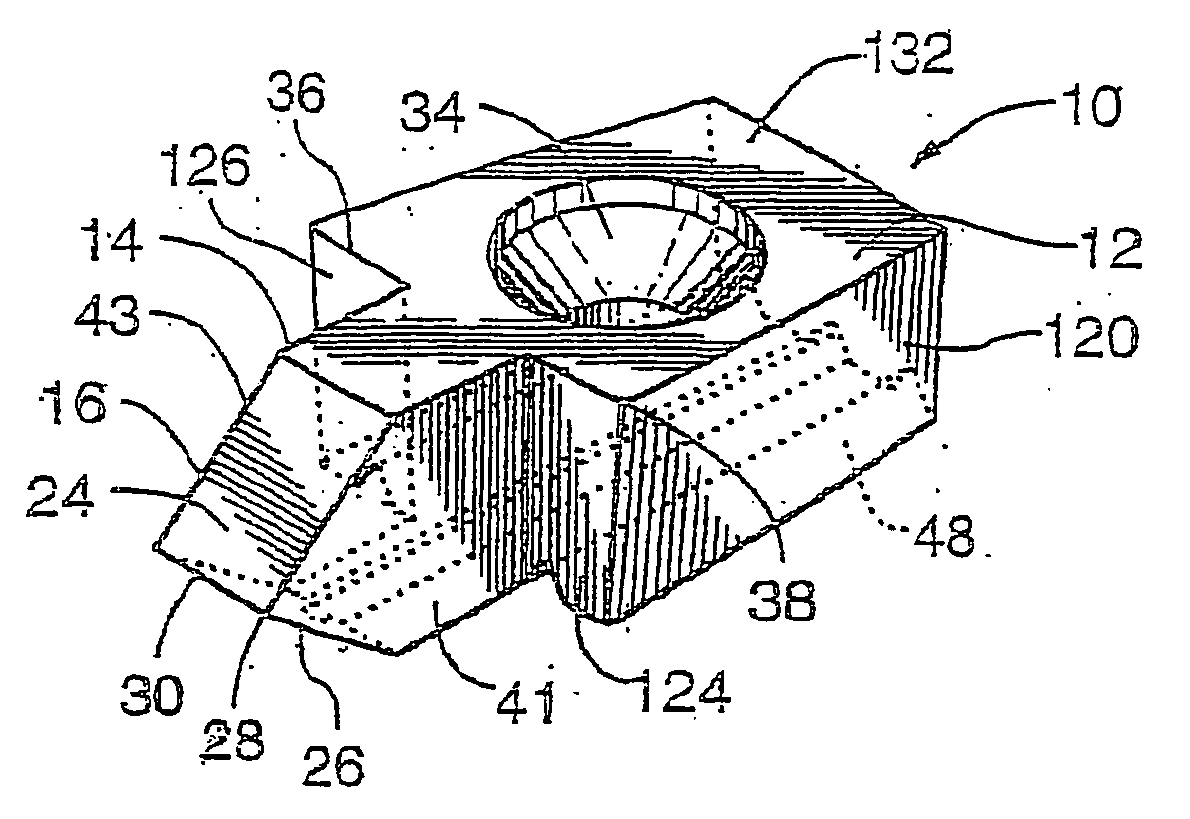
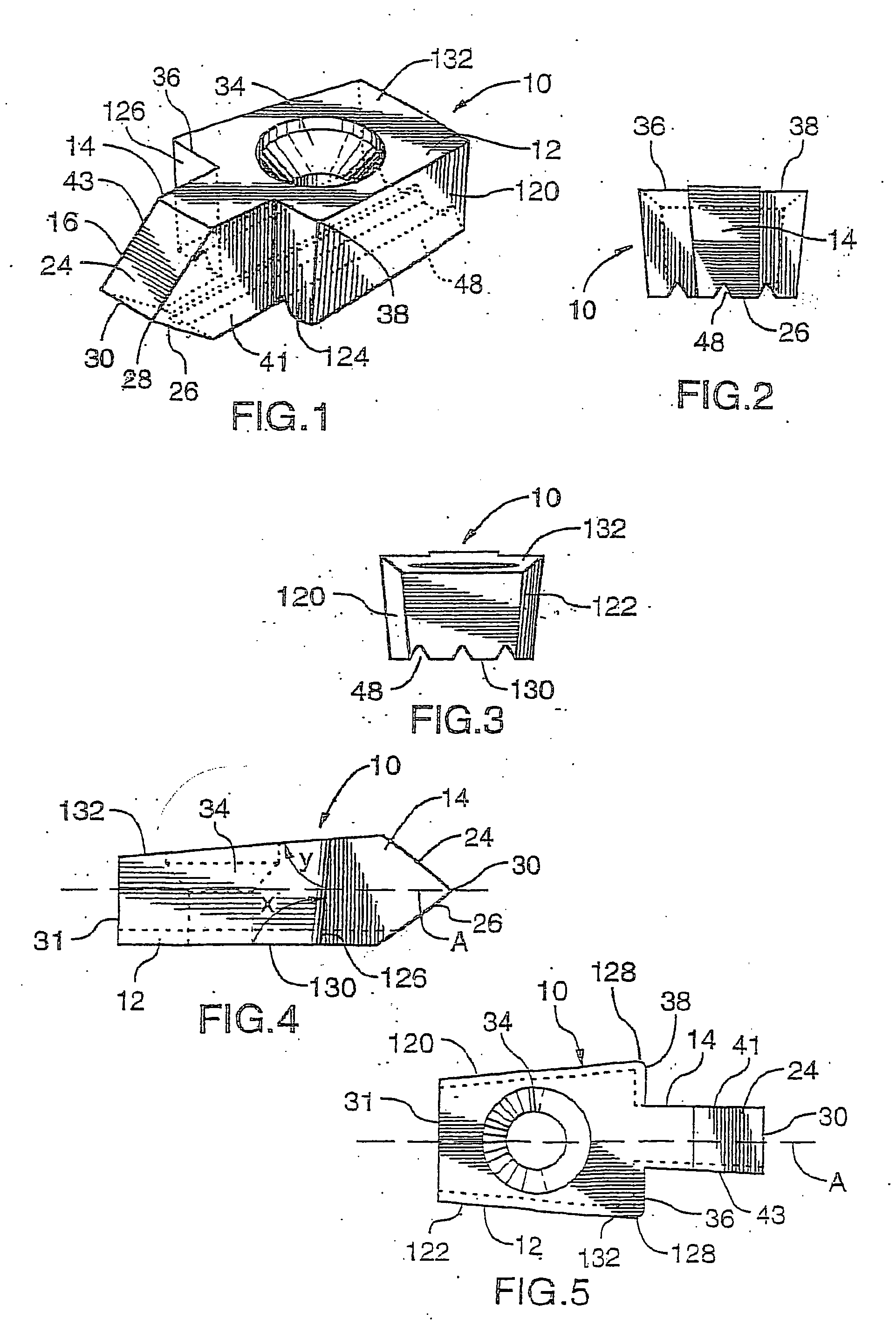
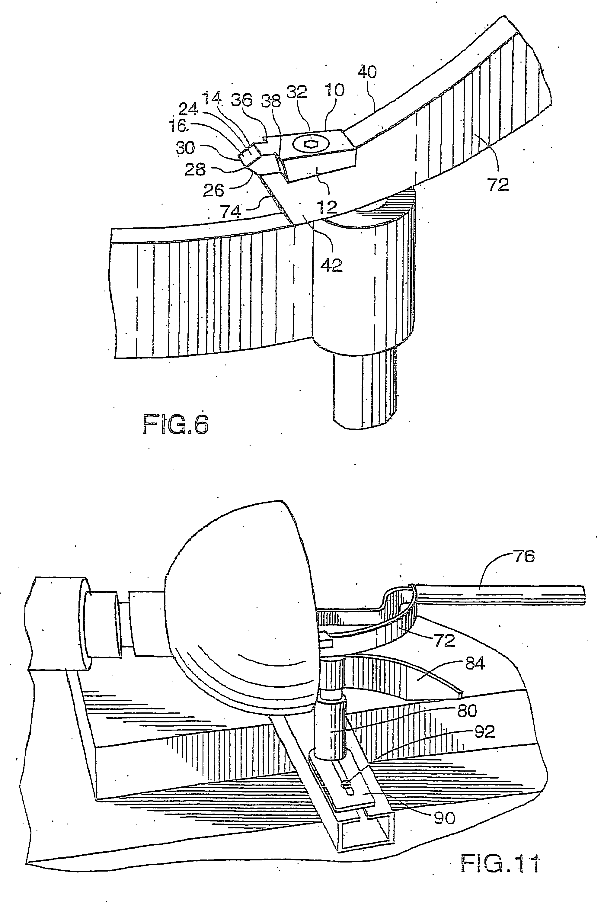
[0035] Shown in FIGS. 1 to 6 is one preferred embodiment of the cutting piece or attachment for cutting a groove in a workpiece such as a wood block. The preferred embodiment of the cutting piece 10 has a rear portion 12 securable to a lead end of a cutting tool and a lead portion 14 which extends forwardly from the rear portion. The lead portion has a front section 16 extending beyond the lead end 74 of a cutting tool 70. The front section has a sloping upper side 24 angled downwardly and forwardly, and a lower side 26 angled upwardly and forwardly. The upper side 24 and lower side 26 meet at a front end 28 of the lead portion to form a leading transverse cutting edge 30. Preferably the upper side 24 and the lower side 26 define an angle not exceeding 90 degrees and more preferably an angle less than 90 degrees. In one preferred embodiment, the acute angle defined between the upper side 24 and the lower side is about 75 degrees and the preferred range for this angle is between 60 a...


PUM

PropertyMeasurementUnit
angleaaaaaaaaaa
angleaaaaaaaaaa
angleaaaaaaaaaa

Abstract

A cutting tool piece is provided including a rear portion and a lead portion, the lead portion including a front section having an upper side angled downwardly and forwardly and a lower side angled upwardly and forwardly to form a transverse lead cutting edge. The rear portion includes a hole to secure the tool piece to a cutting tool and transverse cutting edges extending outwardly from side walls of the front section. A system is also described for cutting a bowl by coring out an interior portion of a wood block by applying the cutting tool which is curved and rotatably mounted to a post. Its lead end with the tool piece attached creates a circular groove. The cutting tool is advanced on a path which curves toward the central axis of the lathe.

Description

RELATED APPLICATIONS [0001] This application is a divisional of U.S. patent application Ser. No. 10 / 469,564 filed Dec. 8, 2003, which is a 371 of PCT / CA02 / 00280 filed Mar. 1, 2002, which claims priority of Canadian Patent Application 2,336,239 filed Mar. 1, 2001.FIELD OF THE INVENTION [0002] This invention relates to a cutting piece, a cutting tool, a system for forming a bowl utilizing a lathe, and a method for using the aforementioned system. BACKGROUND OF THE INVENTION [0003] Lathes are used in the art of carving wood pieces by spinning wood pieces at sufficient speed and applying a sharp instrument to the wood piece for patterning or carving. The lathe typically includes a flat horizontal bed with rails mounted on the bed. Typically a support block or tool rest for supporting a cutting tool is slidably mounted on the bed rails. The cutting tool may be manually applied to the face of a wood block, using the support block or tool rest as a fulcrum to manipulate the tool upon the w...

Claims


Application Information

Patent Timeline
Patent Type & Authority Applications(United States)
IPC IPC(8): B27M3/00B23B5/40B23B27/04B27C7/00B27C7/06B27G15/00
CPCB23B5/40B23B27/04B23B2220/126B23B2260/114Y10T82/10B27C7/06B27G15/00Y10T407/21Y10T407/23B27C7/00
Inventor CLAY, TYMEN
Owner CLAY TYMEN
Learn More