
Tripod foot

a technology of a tripod and a foot is applied in the field of tripods, which can solve the problems of not always possible, the straps used currently are problematic, and the degree of force required to work against the resilience required, and achieves the effects of easy manufacturing, good grip, and increased friction

Active Publication Date: 2020-10-06
VITEC GRP PLC
View PDF64 Cites 0 Cited by
  • Summary
  • Abstract
  • Description
  • Claims
  • Application Information

AI Technical Summary

Benefits of technology

The invention is a securing mechanism for a shelf that reduces the force applied by the user, making it more comfortable and safer. The handle is connected to the foot by two pivot mounts, which increase strength and provide symmetrical distribution of forces. The handle shields the securing member to avoid catching on other items. The technical effects are improved comfort, safety, and efficiency in securing shelves.

Problems solved by technology

However, fitment and removal of straps currently in use requires a degree of force to work against the required resilience of the strap which is required to hold the foot firmly in place for safe operation.
Straps used currently can therefore be problematic in requiring a degree of force to be exerted by the user and therefore for the user to be able to properly grip the strap in order to clip the strap onto and off a tripod leg.
It is not always possible in various outdoor conditions and outdoor circumstances for a user to have the sufficient strength and grip for the necessary force.
This can result in injury to the user particularly in outdoor or adverse weather conditions.

Method used


Image

  • Tripod foot
  • Tripod foot
  • Tripod foot

Examples


Embodiment Construction

[0043]Tripods and other support equipment should ideally be able to accommodate different surface types dependent upon the terrain on which the tripod is to be used. For example, when the tripod is to be used on soft ground, then the base of a leg can be equipped with a small spike which can penetrate the ground and impart thereby stability to the tripod. Such a spike would however, be unsuitable for use on a hard surface such as tiles or floor boards as the frictional force between the end of the spike and the surface would be low, leaving the tripod leg too easily moveable horizontally. A spike may also damage the surface which may not be acceptable.

[0044]To solve this problem, many different methods have been proposed. The present invention is concerned with one particular solution, namely enabling the tripod and other equipment to be attachable to different feet which are exchangeable and replaceable. Current approaches include alternative foot types being clipped onto the end o...


PUM


Abstract

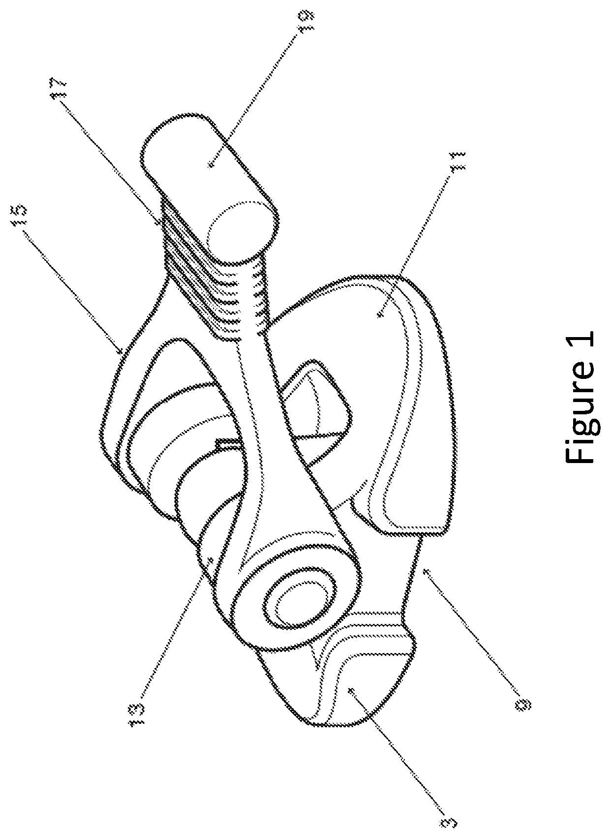
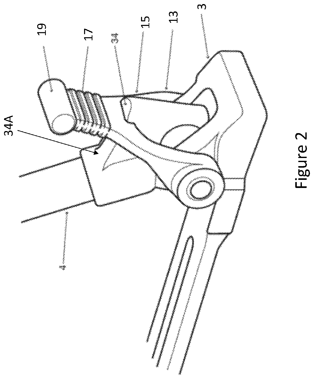
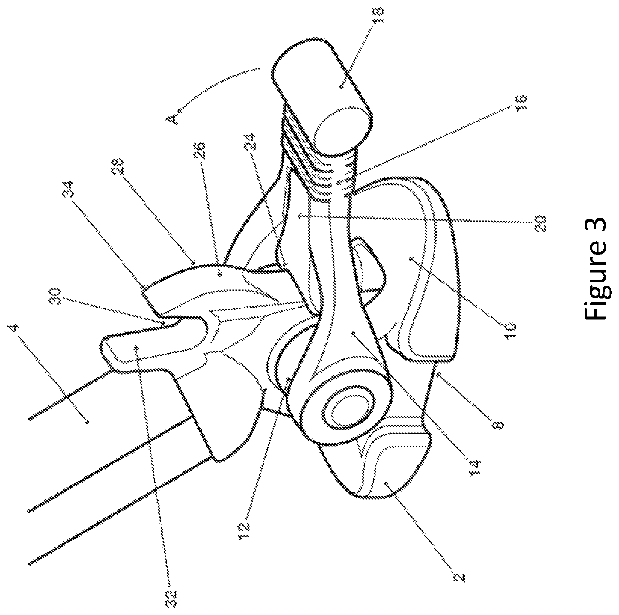
A foot having a base portion and a handle, the handle being pivotally attached to the base portion at a first end and including a gripping portion at a second end, said handle further comprising a centrally deployed securing member attached to the gripping portion, the handle being movable between a first position in which the foot is removable from a leg and a second position in which an end of the securing member is secured within a securing recess in the leg portion whereby the foot is secured to the leg.

Description

CROSS REFERENCE TO RELATED APPLICATIONS[0001]This application is a national phase filing under 35 U.S.C. § 371 of International Patent Application No. PCT / GB2017 / 050768, filed Mar. 20, 2017, which claims priority to Great Britain Application No. 1605836.4 filed Apr. 6, 2016, Great Britain Application No. 1608265.3, filed May 11, 2016, and Great Britain Application No. 1701937.3 filed Feb. 6, 2017, each of which are incorporated herein by reference in their entirety.FIELD OF THE INVENTION[0002]The invention relates to a means of removable attachment of a foot to a leg of a support structure. The means is disclosed particularly for use in association with the leg of a tripod.BACKGROUND TO THE INVENTION[0003]Tripods are widely used as platforms for supporting, in a stable manner, equipment such as cameras for maintaining the stability of a camera during the camera's use. During such use the tripod may need to be transferred from one surface to another.[0004]As such, tripods and other s...

Claims


Application Information

Patent Timeline
Patent Type & Authority Patents(United States)
IPC IPC(8): F16M11/36F16M11/24G03B17/56
CPCF16M11/36G03B17/56F16M11/247G03B17/561F16M2200/02F16M2200/08A47B91/00F16B2/18F16M11/20F16M11/24F16M11/32
Inventor MURROW, ANDREW DEREK
Owner VITEC GRP PLC
Learn More