Extreme ultra violet light source device
- Summary
- Abstract
- Description
- Claims
- Application Information
AI Technical Summary
Benefits of technology
Problems solved by technology
Method used
Image
Examples
first embodiment
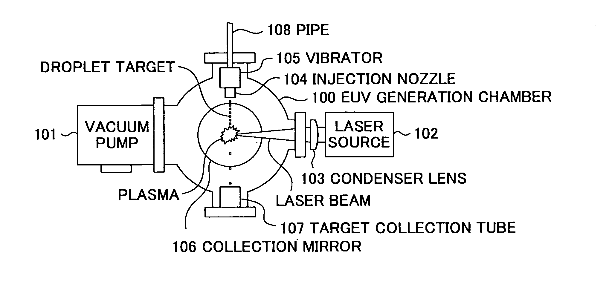
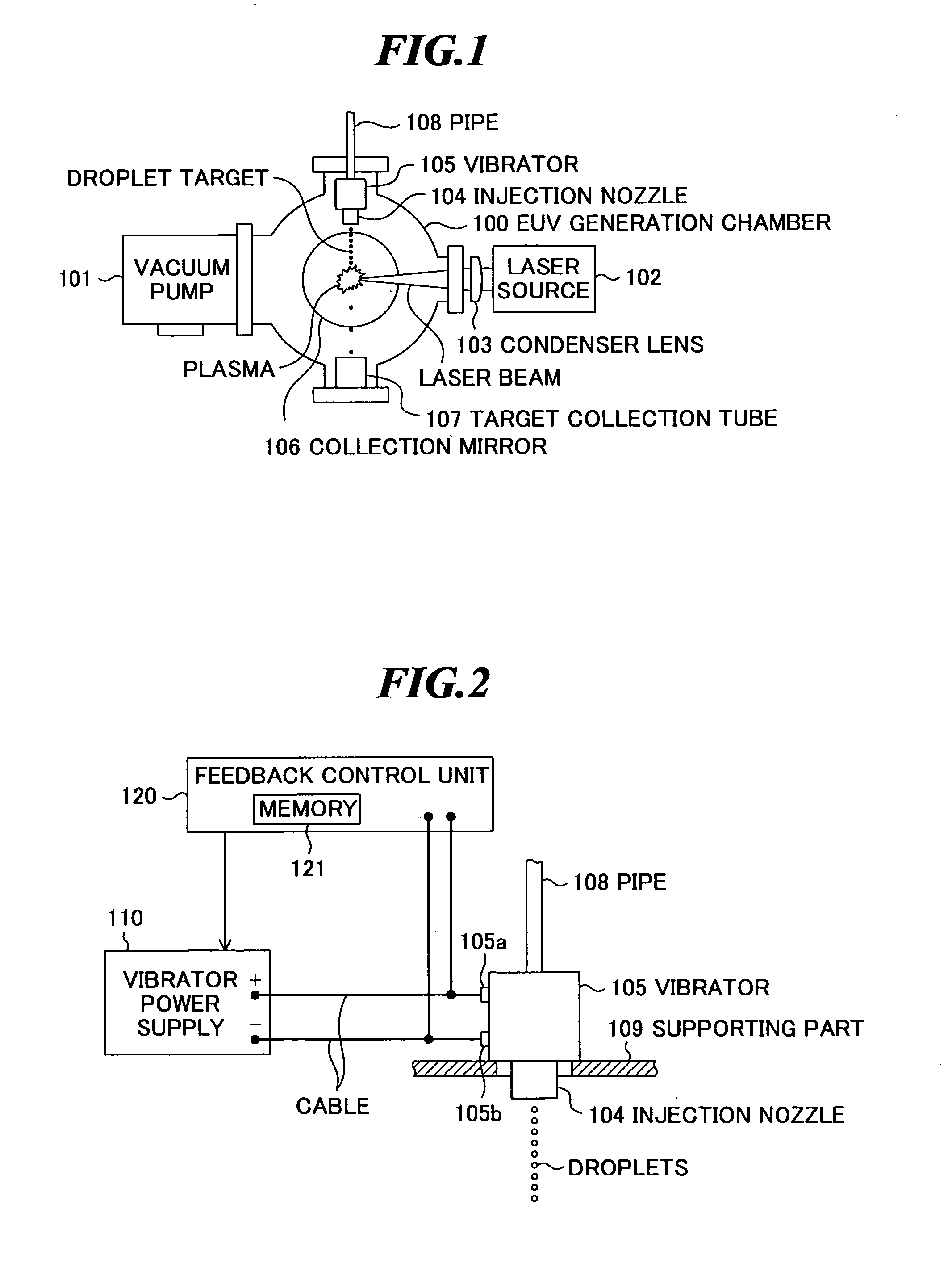
[0036]FIG. 2 is a schematic diagram showing a part of the LPP extreme ultra violet light source device according to the present invention, and shows the constitution of the injection nozzle 104 and vibrator 105 as shown in FIG. 1 in detail.
[0037] As shown in FIG. 2, the injection nozzle 104 is provided with a pipe 108 for supplying the target material to the injection nozzle 104. Further, the vibrator 105 is supported by a supporting part 109 fixed to the EUV generation chamber 100 (FIG. 1). The vibrator 105 is provided with two terminals 105a and 105b, and a vibrator power supply (voltage generator) 110 for generating a drive signal having a predetermined frequency to supply a voltage of the drive signal to the vibrator is connected to these terminals 105a and 105b via a cable. Furthermore, a feedback control unit 120 for feedback controlling the output voltage of the vibrator power supply 110 is provided to the vibrator power supply 110.
[0038] In the embodiment, a liquid target m...
second embodiment
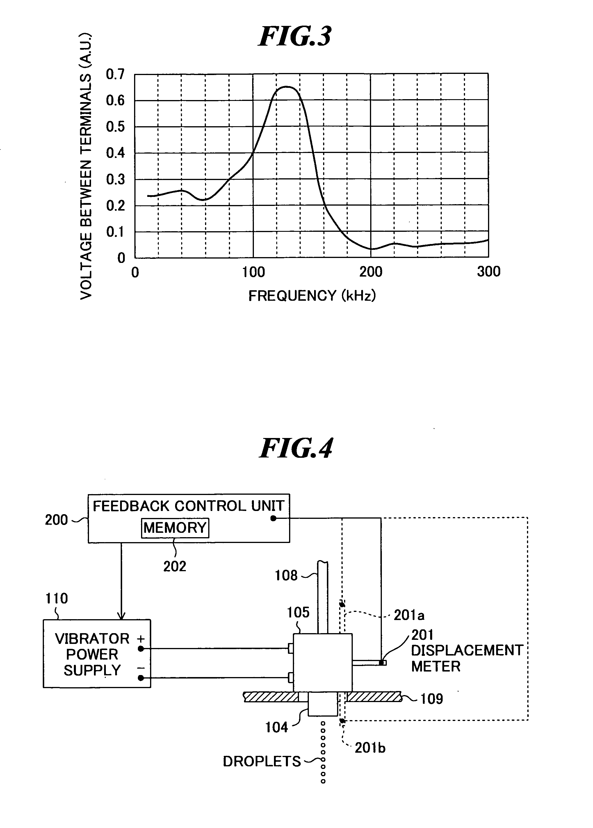
[0050]FIG. 4 is a schematic diagram showing a part of the LPP extreme ultra violet light source device according to the present invention. This LPPEUV light source device has a feedback control unit 200 in place of the feedback control unit 120 shown in FIG. 2, and further has at least one contact-type displacement meter (displacement gage) 201 as a measuring unit attached to the vibrator 105. Other constitution is the same as that of the LPP EUV light source device shown in FIGS. 1 and 2.
[0051] The displacement meter 201 is provided for measuring the amount of displacement of the vibrator 105. Further, the feedback control unit 200 feedback controls the output voltage of the vibrator power supply 110 based on the amount of displacement measured by the displacement meter 201 such that the vibrator 105 vibrates with desired amplitude (amplitude in a range in which uniform droplets can be formed). For example, the feedback control unit 200 has a nonvolatile memory 202 in which a datab...
third embodiment
[0056]FIG. 5 is a schematic diagram showing a part of the LPP extreme ultra violet light source device according to the present invention. This LPP EUV light source device has a feedback control unit 300 in place of the feedback control unit 120 shown in FIG. 2, and further has at least one contact-type displacement meter 301 as a measuring unit attached to the injection nozzle 104. Other constitution is the same as that of the LPP EUV light source device shown in FIGS. 1 and 2.
[0057] The displacement meter 301 is provided for measuring the amount of displacement of the injection nozzle 104. Further, the feedback control unit 300 feedback controls the output voltage of the vibrator power supply 110 based on the amount of displacement measured by the displacement meter 301 such that the injection nozzle 104 vibrates with desired amplitude (amplitude in a range in which uniform droplets can be formed). For example, the feedback control unit 300 has a nonvolatile memory 302 in which a ...
PUM
 Abstract
Description
Claims
Application Information
 - R&D
- Intellectual Property
- Life Sciences
- Materials
- Tech Scout
- Unparalleled Data Quality
- Higher Quality Content
- 60% Fewer Hallucinations
Browse by: Latest US Patents, China's latest patents, Technical Efficacy Thesaurus, Application Domain, Technology Topic, Popular Technical Reports.
© 2025 PatSnap. All rights reserved.Legal|Privacy policy|Modern Slavery Act Transparency Statement|Sitemap|About US| Contact US: help@patsnap.com


