Compressible fluid pressure actuator
a technology of compressible fluid and actuator, which is applied in the direction of servomotors, machines/engines, manufacturing tools, etc., can solve the problems of actuators, actuator response, actuator drop, etc., and achieve the effects of enhancing response, maintaining flexibility, and ensuring safety
- Summary
- Abstract
- Description
- Claims
- Application Information
AI Technical Summary
Benefits of technology
Problems solved by technology
Method used
Image
Examples
first embodiment
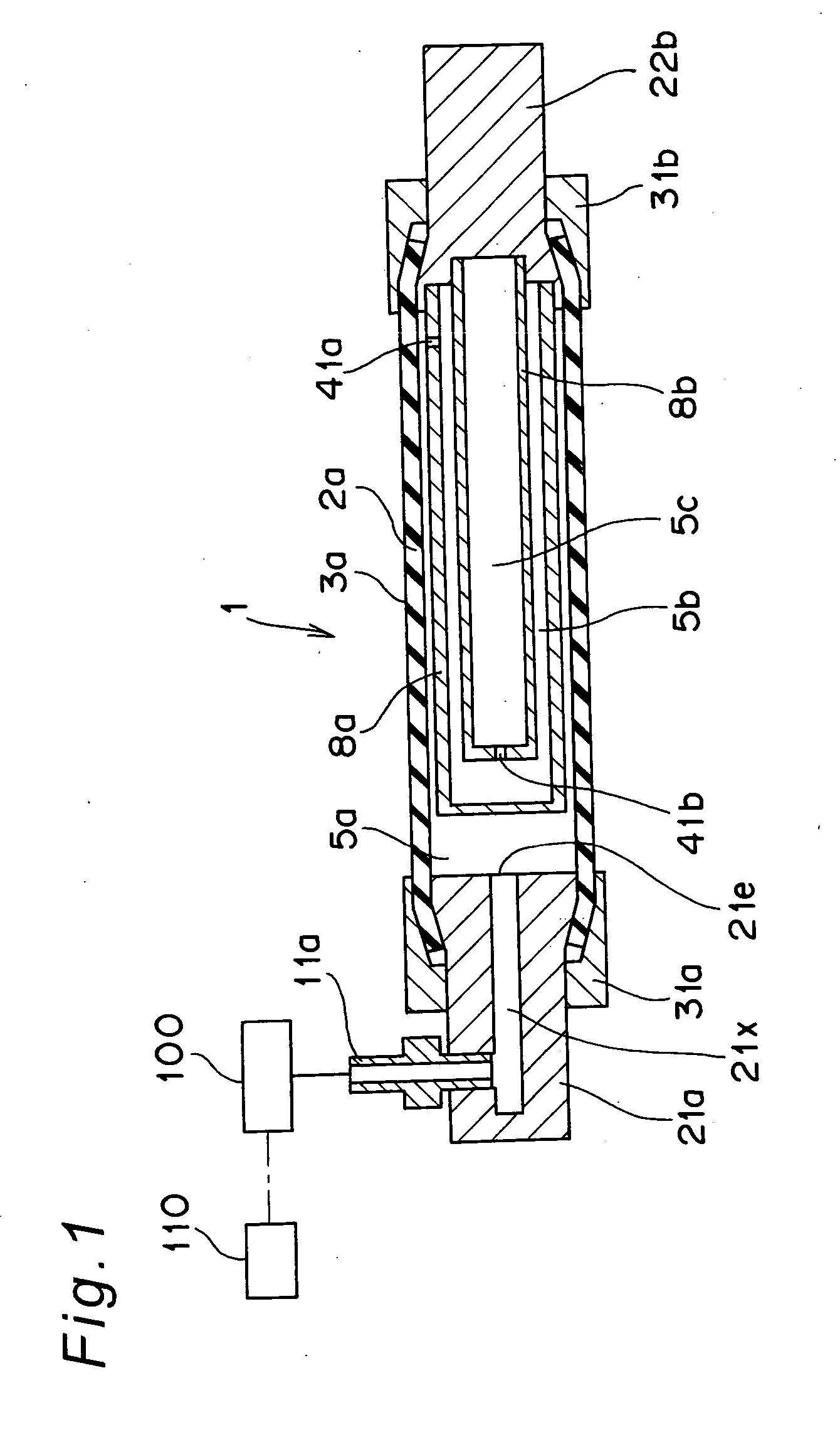
[0095]FIG. 1 is a cross sectional view showing an outline of a pneumatic actuator 1 serving as one example of a compressible fluid pressure actuator according to a first embodiment of the present invention. In FIG. 1, reference numeral 2a is a first tube-like elastic body, which includes a space inside and is made of rubber or rubber-like elastic body, functioning as one example of a first tubular expandable member. Reference numeral 3a is a deforming direction regulating member, in which resin or metal fiber code that is not easily stretched in terms of material is woven in a mesh shape so that the deformation in the radial direction due to the expansion of the first tube-like elastic body 2a is converted to the contraction of the length in the axial direction and so that the deformation in the radial direction due to the contraction of the first tube-like elastic body 2a is converted to the expansion of the length in the axial direction, and is arranged so as to cover the exterior...
second embodiment
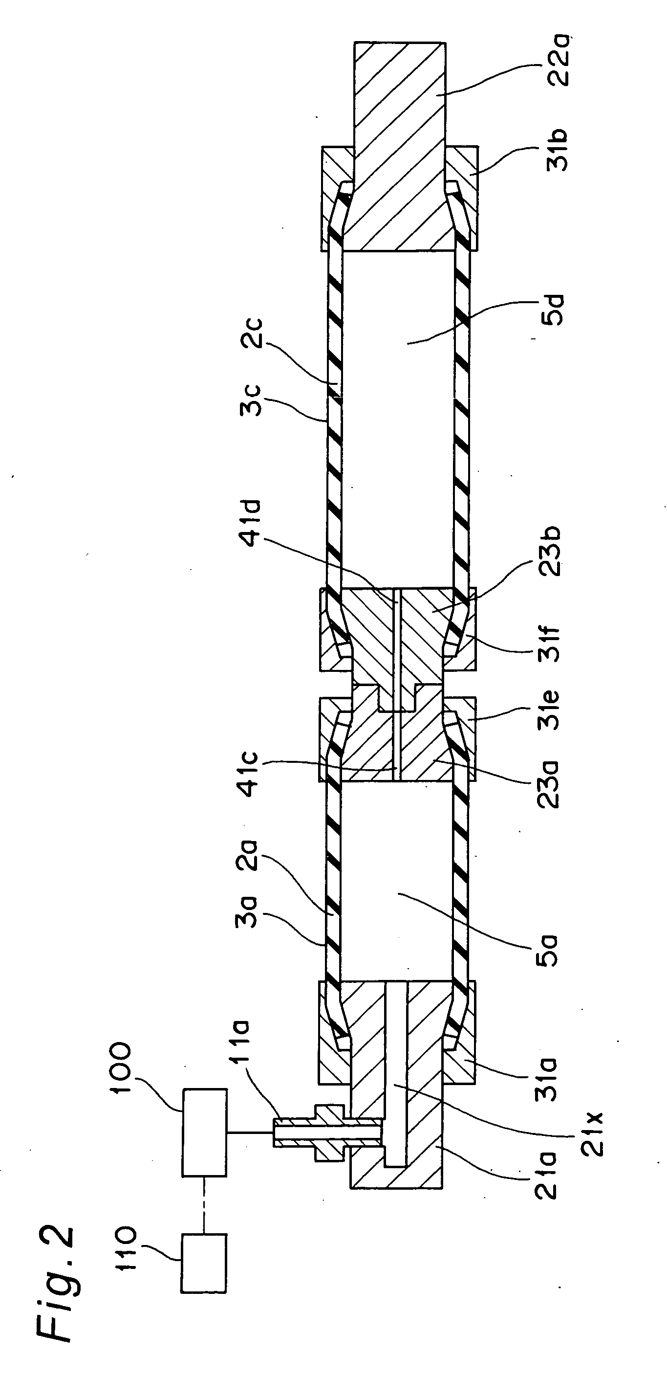
[0104]FIG. 2 is a cross sectional view showing the outline of a second embodiment of the pneumatic actuator according to the present invention. The portions functioning similar to the first embodiment described above are denoted with the same reference characters and redundant explanation is omitted. In the second embodiment, both ends of the first tube-like elastic body 2a are sealed with the inner side sealing parts 21a, 23a serving as one example of sealing means and the outer side sealing parts 31a, 31e serving as one example of the fixed means with respect to the pneumatic actuator including the first tube-like elastic body 2a. Both ends of the second tube-like elastic body 2c serving as one example of the second tubular expandable member, which exterior surface is covered by the deforming direction regulating member 3c similar to the deforming direction regulating member 3a, are sealed with the inner side sealing parts 22a, 23b serving as one example of the sealing means and t...
third embodiment
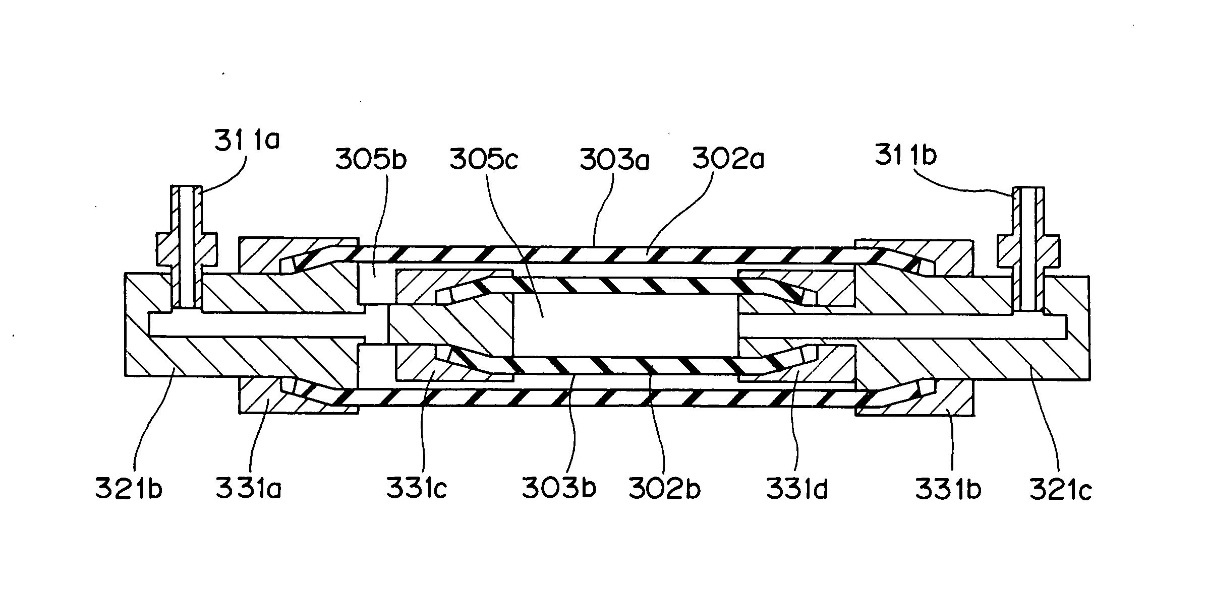
[0110]FIG. 5 is a cross sectional view showing an outline of a third embodiment of the pneumatic actuator according to the present invention. The portions functioning similar to the second embodiment described above are denoted with the same reference characters and redundant explanation is omitted. In third embodiment, the first and second bellows shaped elastic bodies 4a, 4b are used in place of the first and the second tube-like elastic bodies 2a, 2c in the second embodiment. The entire length of the tube-like elastic body becomes short as the inner pressure increases, whereas the entire length of the first and second bellows shaped elastic bodies 4a, 4b becomes long as the inner pressure increases. However, since the pneumatic actuator using the first and second bellows shaped elastic bodies 4a, 4b similarly exhibits the response of substantially primary delay system, no significant difference exists in the effect of arranging the pressure loss part. Thus, the present invention ...
PUM
 Abstract
Description
Claims
Application Information
 - R&D
- Intellectual Property
- Life Sciences
- Materials
- Tech Scout
- Unparalleled Data Quality
- Higher Quality Content
- 60% Fewer Hallucinations
Browse by: Latest US Patents, China's latest patents, Technical Efficacy Thesaurus, Application Domain, Technology Topic, Popular Technical Reports.
© 2025 PatSnap. All rights reserved.Legal|Privacy policy|Modern Slavery Act Transparency Statement|Sitemap|About US| Contact US: help@patsnap.com


