Eureka AIR delivers breakthrough ideas for toughest innovation challenges, trusted by R&D personnel around the world.

Intelligent valve control methods and systems

Inactive Publication Date: 2006-08-10
ZHANG JACK K
View PDF0 Cites 212 Cited by
  • Summary
  • Abstract
  • Description
  • Claims
  • Application Information

AI Technical Summary

Benefits of technology

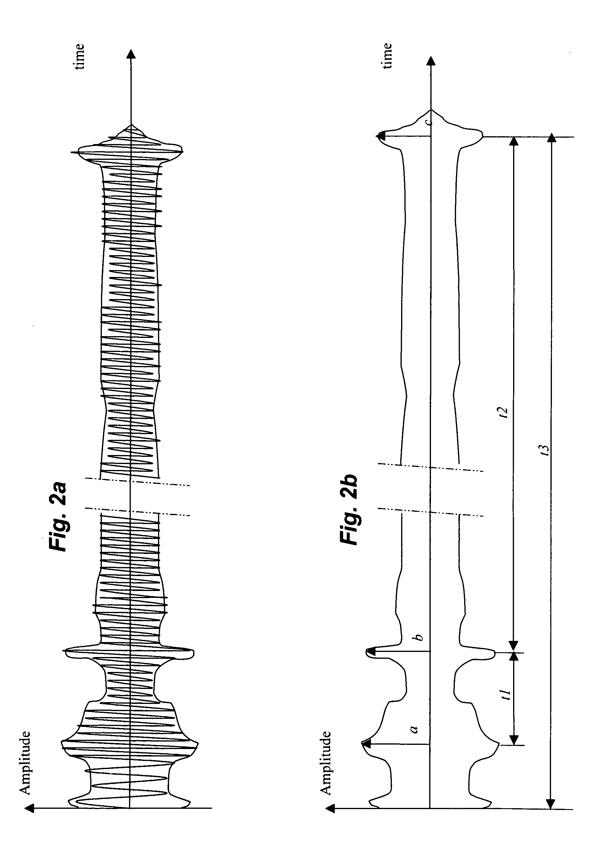
[0032] In accordance with an aspect of the present invention, a method is provided for detecting and determining the occurrence of an event that is likely to cause water damage. The method comprises monitoring sound and / or vibration occurred in the pipe that carries the liquid, such as water. When liquid flows through pipes and regulating valve, sound and vibration occur. The frequencies of these vibrations spread over a wide range. Some are in human audible range and can be detected by human and microphones. Only instruments can detect other vibration components. Because liquid and / or pipes used to carry liquids are typically good sound and vibration conductors, sound and vibrations can be readily detected by transducers, such as surface microphones and accelerometers, coupled to a pipe or submerged in the liquid. Liquid flow vibration can be differentiated from other vibration when time, frequency and patterns are analyzed. A flow sound tends to have consistent components when analyze over time. Therefore, sound and vibration signal can be useful for monitoring the occurrence of liquid flow of mentionable quantity.
[0066] There are distinctive advantages of using modulated vibration and sound for communication over the water pipes. First, both base station and remote modules are already equipped with transducers. Second, vibration or sound over water pipes, which typically made of good sound conductor, can travel a long distance from point to point. Third, sound or vibration over pipes is immune to electricity or radio wave interference, thus more reliable and robust.

Problems solved by technology

When liquid flows through pipes and regulating valve, sound and vibration occur.

Method used


Image

  • Intelligent valve control methods and systems
  • Intelligent valve control methods and systems
  • Intelligent valve control methods and systems

Examples


Embodiment Construction

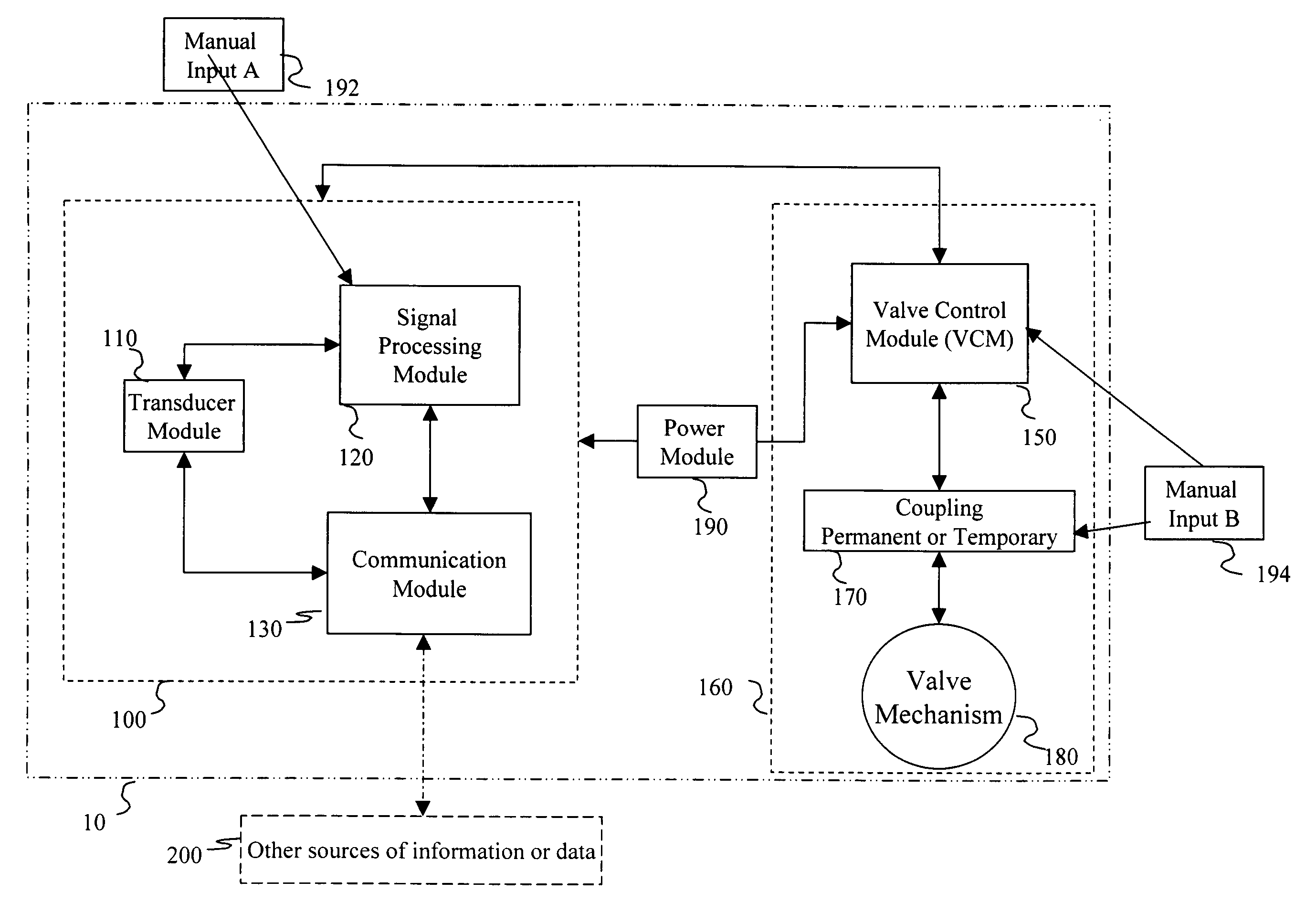
[0075] On FIG. 1, a monitoring system 10 according to the present invention is shown to include functional Detection Module (DM) 100. DM 100 comprises a Transducer module 110 for detecting vibration signal. For 110 to function, at least one vibration sensor, an accelerometer or a microphone is provided with appropriate power supply. Most vibration sensors today are either piezoelectric or piezo-resistive. Piezoelectric transducers are typically good for vibrations of higher frequencies, although peizo-film enables measurement of lower frequencies. Piezo-resistive sensors are good for low frequencies, such as MEM accelerometers, are inexpensive and small. Microphones are a variation of the vibration sensor optimized to detect certain frequency range in a structure or over the air. For use with the present inventions, small microphones are preferred. In this disclosure, vibration transducers are used to include terms covered by accelerometers, vibration sensors and microphones regardl...


PUM


Abstract

A method for determining a burst pipe that requires immediate feeding-valve closing using acoustic and / or vibration sensors coupled to the pipe lor detecting signals, a microprocessor for analyzing signals from said sensors in real-time, a memory coupled to said microprocessor for storing data, including digital signatures acoustic and / or vibration signatures, as well as an actuator electrically coupled to said microprocessor and mechanically coupled to said feeding-valve. When the sensor signals match stored leak-signatures or when a persistent sensor signal produces no match, the system of the present invention initiates a valve closing. To improve detection, signals from other sensors, i.e. water sensors, smoke detectors, heat sensors or acoustic / vibration sensors mounted on other pipes are also used. Some of the said systems have IP addresses and can communicate over the Internet or wirelessly with others.

Description

FIELD OF THE INVENTION [0001] The present invention generally relates to systems designed to detect gas or liquid leaks from pipes in a building or other carrying infrastructure. More specifically, the present invention relates to systems designed to (1) detect water or gas leaks based on analysis of vibration and sound signals along with other information; and (2) automatically shut off a leaking water or gas infrastructure. BACKGROUND OF THE INVENTION [0002] Household and commercial building water flooding from water systems costs homeowners, businesses and insurance companies more than $100 million every year in the United States alone. Burst pipes from freezing, broken plumbing fixtures or malfunctioning appliances are common causes for water flooding within buildings. [0003] For example, flooding of laundry rooms is such a common occurrence. It is estimated that the unrestricted flow through the hoses of washing machine reaches 3 gallons per minute or 180 gallons an hour. Clear...

Claims


Application Information

Patent Timeline
IPC IPC(8): G01N29/14G01M3/24G05D7/06
CPCG01M3/243G01N29/14G01N29/222G01N29/4418G01N29/46G01N2291/02836H04Q9/00G01F1/666
Inventor ZHANG, JACK K.
Owner ZHANG JACK K
Why Eureka
Eureka Blog
Learn More