
Syringe drive system

a drive system and syringe technology, applied in the field of medical syringes, can solve the problems of increasing the sophistication of these devices, preventing wider use of most such drivers, and inconsistent treatment modality,

Inactive Publication Date: 2006-08-03
INFUSIVE TECH LLC
View PDF16 Cites 104 Cited by
  • Summary
  • Abstract
  • Description
  • Claims
  • Application Information

AI Technical Summary

Benefits of technology

[0035] To satisfy both of these conditions a spring is disposed in the snap-on apparatus proximally disposed relation relative to the collet-button. A pawl is provided to interface with the ratchet pattern of the outer rim of the collet-button to limit articulation of the collet-button to a direction of rotation which stores energy into the spring rather than to drive the stem to directly dispense fluid from the syringe. Note that the stem of the syringe may be retracted a short distance (compressing the spring) to test for blood flash while articulation of the collet-button simply stores energy in the spring which reactively displaces the stem to dispense fluid from the syringe with forces restricted to the force which may be stored in the spring. Note that, once a spring is fully compressed, no additional force may be applied to the stem by rotating the collet-button.
[0058] It is an object to provide the lock apparatus with at least one direction retarding pawl and a collet-button with corresponding ratchet teeth to thereby restrict collet-button rotation to a single direction such that collet-button rotation displaces the collet-button away from said syringe barrel.

Problems solved by technology

However, while syringe drivers are used for such purposes in large numbers in U.S. Hospitals, cost of most such drivers often precludes wider use.
Specialized use of syringe drivers in hospitals has resulted in ever increasing sophistication of these devices.
Nursing home care is a very cost conscious environment where IV therapy is a common, but not consistent treatment modality.
In such cases, syringe drivers or pumps may be capital intensive, but still are desirable in a work environment which is personnel limited.
One of the limitations of use of syringe drivers is a lack of an inherent flushing system.

Method used


Image

  • Syringe drive system
  • Syringe drive system
  • Syringe drive system

Examples


Embodiment Construction

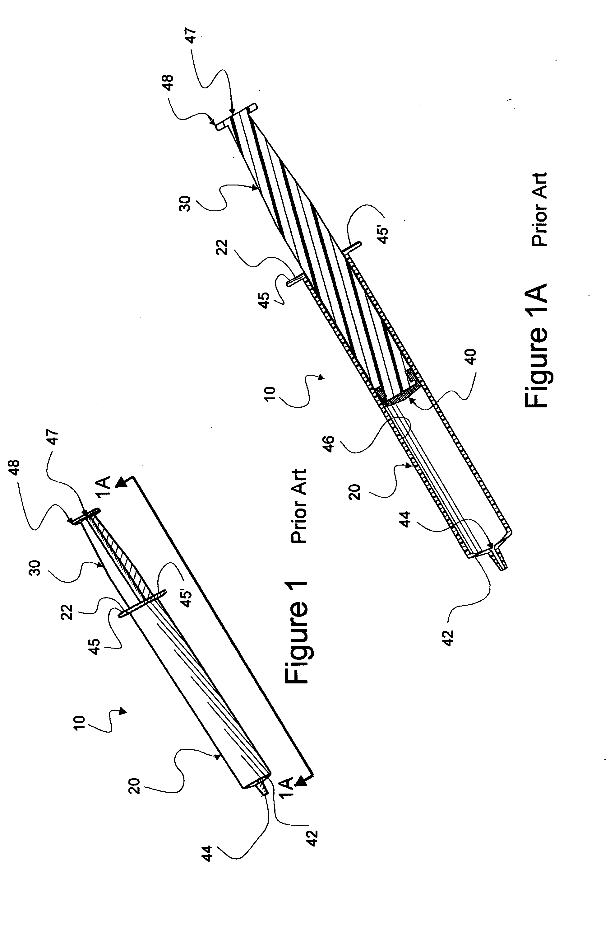
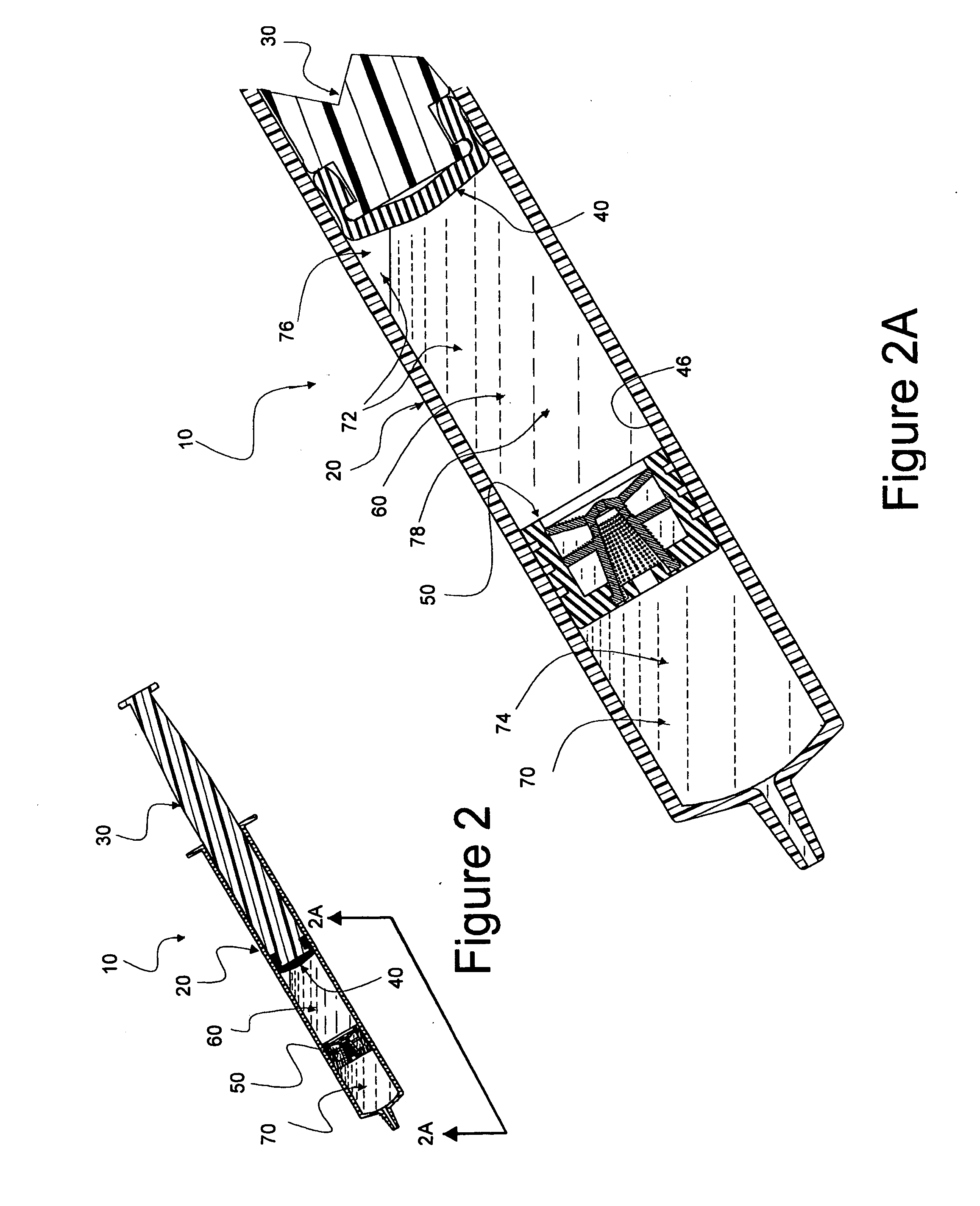
[0101] This invention is supportive of both single chamber syringes and multi-chamber syringes such as those disclosed in U.S. patent application Ser. No. 10 / 838,101, titled MULTI-CHAMBER, SEQUENTIAL DOSE DISPENSING SYRINGE and filed May 3, 2004 by Howlett, et al (Howlett '101). Multi-chamber syringe parts seen in FIGS. 2 and 2A are disclosed in detail in Howlett '101 and are included by reference herein.

[0102] In this description, the term proximal is used to indicate a portion of a device normally closer to a clinician using the device or, in other words away from a patient. The term distal refers to an oppositely disposed portion. Reference is now made to embodiments illustrated in FIGS. 1-31 wherein like numerals are used to designate like parts throughout. Primes of numbers are used to represent parts which are similar, but not identical to other parts having the same numbers.

[0103] As used herein, the term “fluid” is defined to be a substance (either liquid or gas) which ten...


PUM


Abstract

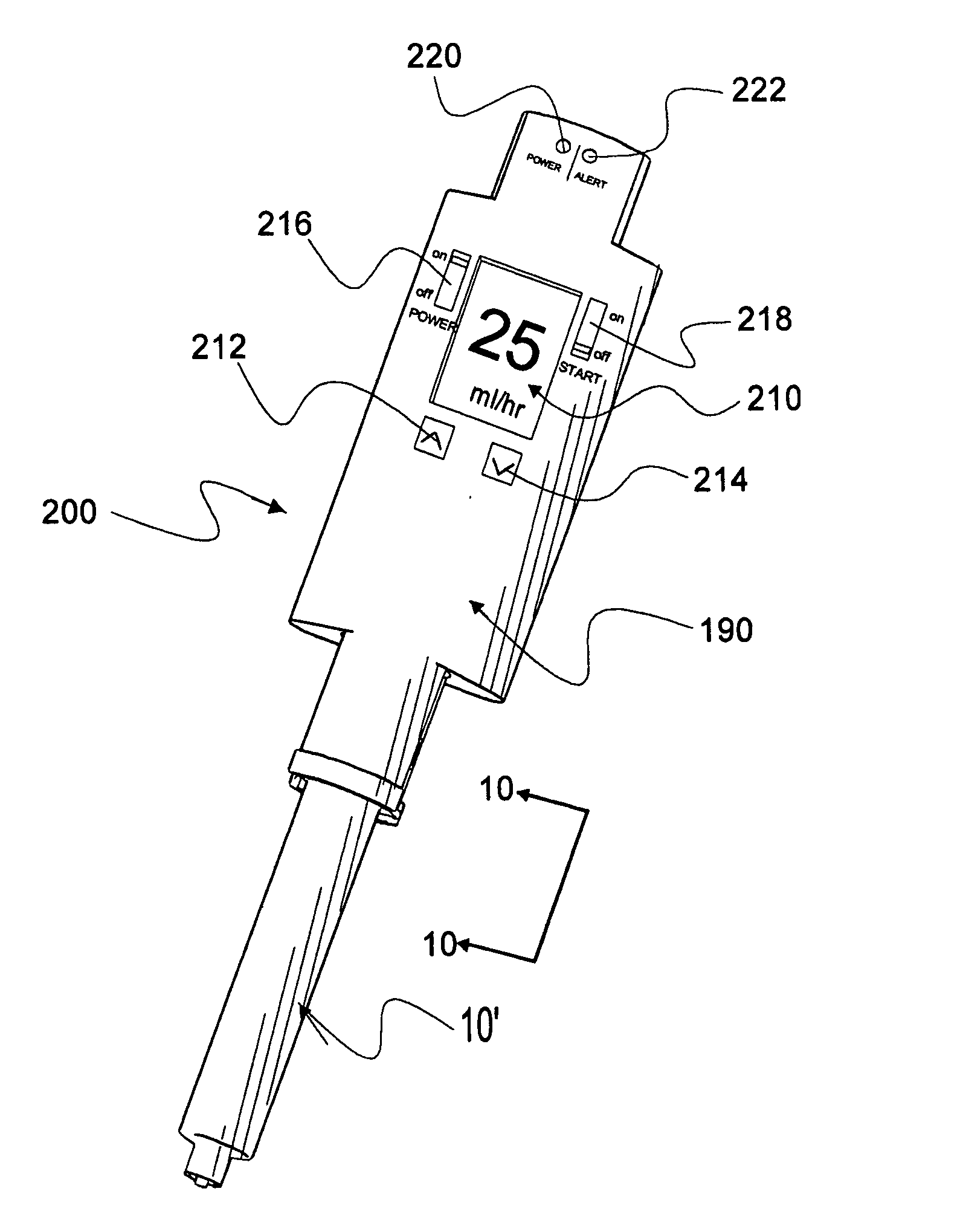
A syringe driver or pump system based upon a syringe stem and associated assembly having a spiral threaded pattern along the outer surface of the stem, a collet-button which is displaceable along the stem assembly (as a nut is displaced along a bolt) and a spring. All are disposed to provide a cam action, translating rotary activity of the collet-button, which tends to be displaced to compress the spring when rotated, to linear displacement as the force of energy is released from the spring when compressed. Thus, force available for driving effluent fluid flow from the syringe is limited by the energy available from the spring, rather than force and energy which might be directly applied to otherwise displace the syringe stem assembly and collet-button. A digitally activated syringe driver and an electrical motor activated driver is disclosed. A number of electronic control systems for the motor are also disclosed.

Description

FIELD OF INVENTION [0001] Inventions which are disclosed herein are related to medical syringes having a barrel and a piston for displacing fluids within the barrel and more specifically to powered systems which are used to drive such syringes to both dispense and draw-up medications and other fluids from and into syringes. BACKGROUND AND DESCRIPTION OF RELATED ART [0002] While syringes comprising a barrel and an associated piston have been used in the medical arts for a very long time, use and makeup of syringes are undergoing constant change to keep up with an ever evolving pattern of medical practice. [0003] As examples, needle-bearing syringes are increasingly employing some form of needle guard to protect against dangers of needle sticks. Use of needleless syringes to deliver medications and to flush indwelling catheters is becoming increasingly prevalent and is the standard of practice in many healthcare facilities. Contemporary medications often require timed delivery at cont...

Claims


Application Information

Patent Timeline
IPC IPC(8): A61M37/00A61M31/00
CPCA61M5/14244A61M5/1454A61M5/1456A61M2205/502
Inventor THORNE, GALE H. JR.THORNE, GALE H.HOWLETT, MICHAEL WALLACE
Owner INFUSIVE TECH LLC
Learn More