
Optical film structure, illlumination apparatus and liquid crystal display device

a technology of optical film and illluminating apparatus, which is applied in the direction of lighting and heating apparatus, planar/plate-like light guides, instruments, etc., can solve the problems of increasing the weight of diffusion plates resulting from the increase of thickness and plate area, increasing the risk of warp and distortion of films, and achieving the effect of maintaining the flatness of optical films

Inactive Publication Date: 2006-08-03
3M INNOVATIVE PROPERTIES CO
View PDF7 Cites 50 Cited by
  • Summary
  • Abstract
  • Description
  • Claims
  • Application Information

AI Technical Summary

Benefits of technology

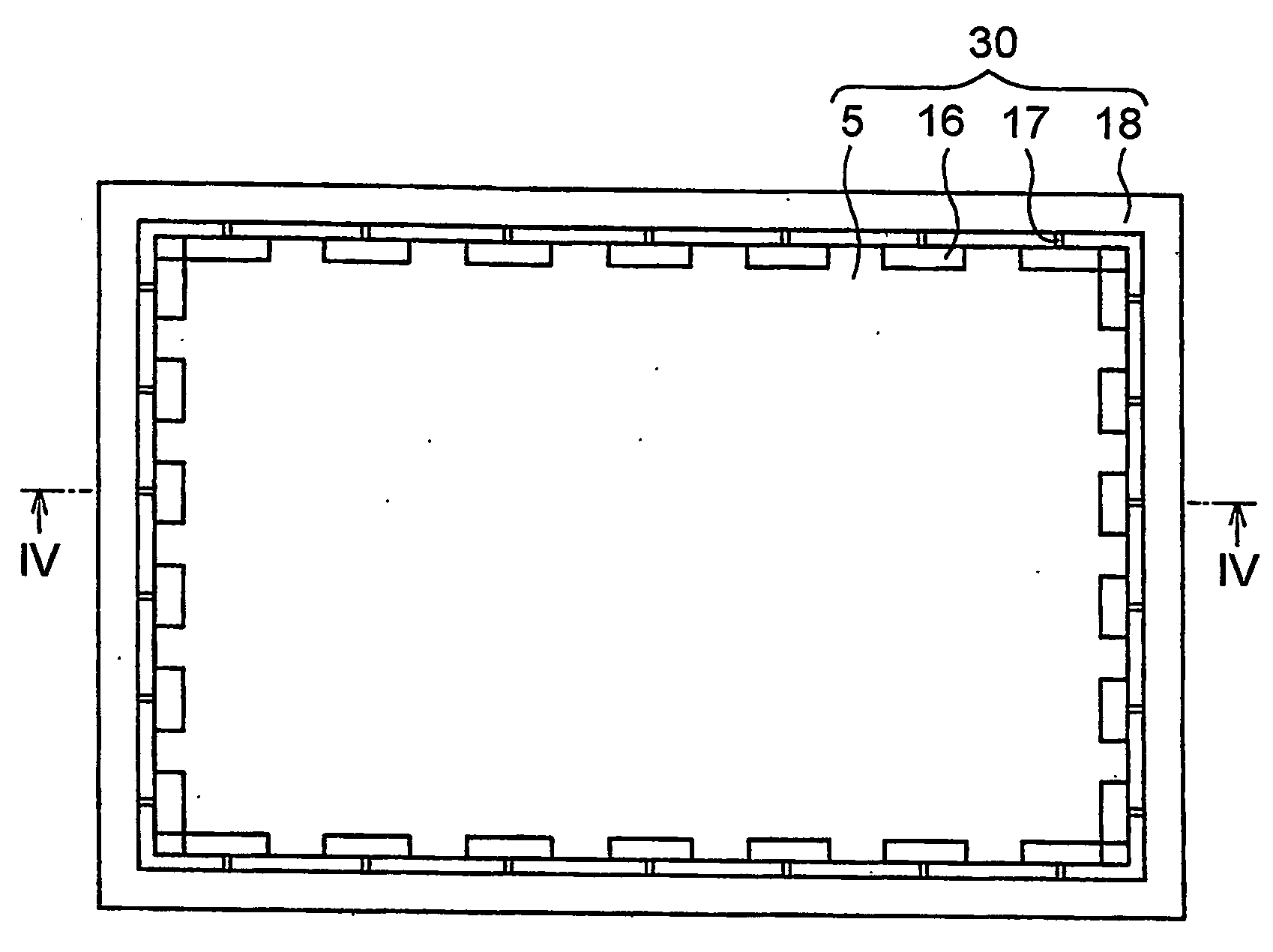
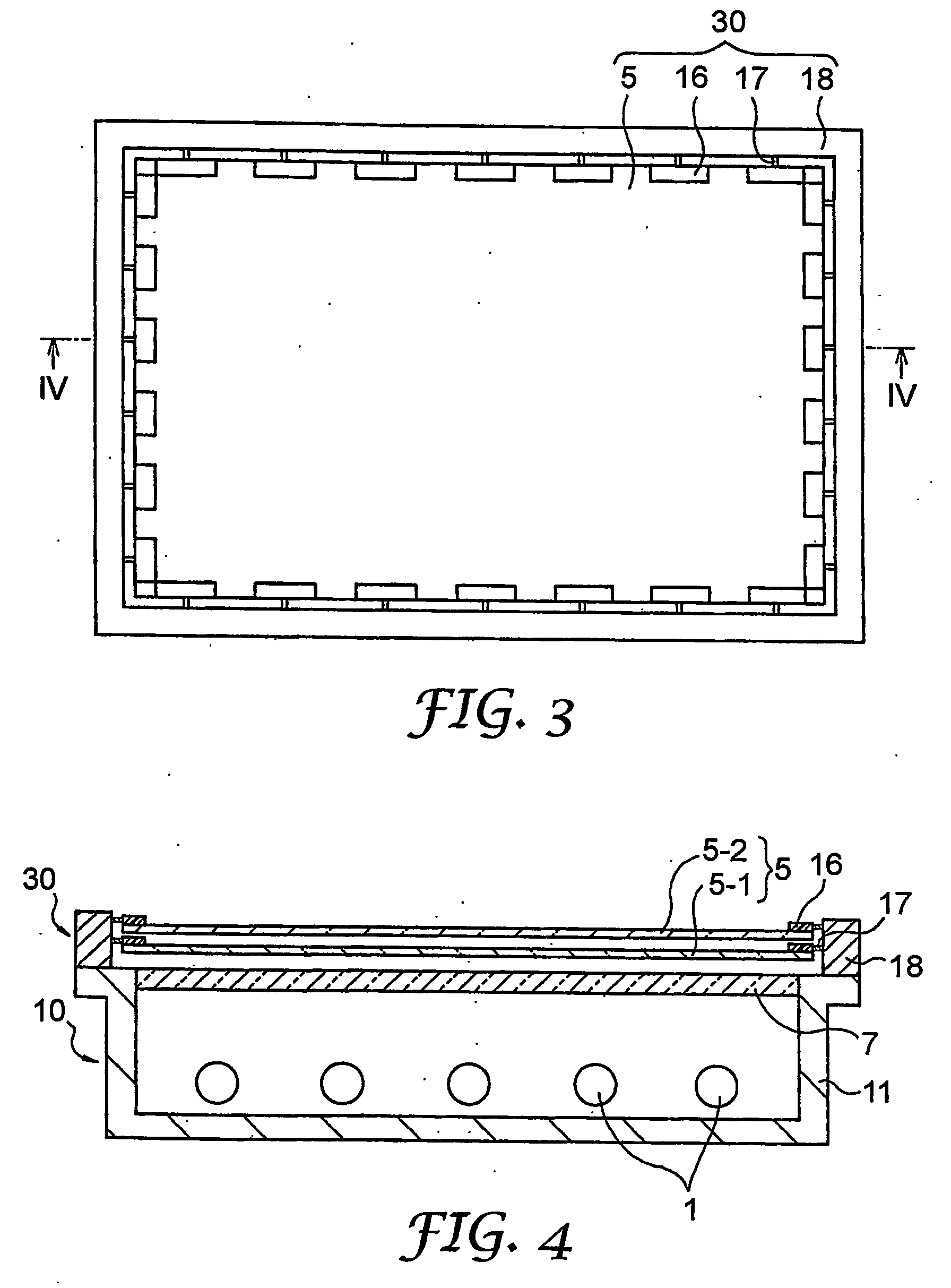
[0028] According to one aspect of the invention, there is provided an optical film structure disposed on a light transmission surface of an illumination unit, for modulating light emitted from the illumination unit and projecting modulated light, comprising at least one optical film; at least four optical film fixing parts disposed at an outer peripheral portion of the optical film; a film tension controlling member attached at one of the end

Problems solved by technology

When the plate is thin, a uniform luminance distribution cannot be obtained easily due to warp and undulation of the plate.
On the other hand, the increase of the weight of the diffusion plate resulting from the increase of the thickness and the area of the plate has become another problem.
However, warp and distortion of the film has become more likely to occur in recent years due to the increase in the size of the liquid crystal display devices.
However, a new problem develops in that the attenuation ratio of transmitted light becomes higher with the increase of the thickness of the optical film and the luminance improving effect drops.
Nonetheless, when this stacking method is employed, a problem arises in that the number of optical films increases and the assembly work of a group of optical films into the liquid crystal display device becomes complicated.
Furthermore, the problems of the occurrence of static electricity and disposal of the wastes occur, too.
In addition, when the light diffusion films are used under the stacked state as described above, the problem of the warp or distortion of the films is unavoidable.

Method used


Image

  • Optical film structure, illlumination apparatus and liquid crystal display device
  • Optical film structure, illlumination apparatus and liquid crystal display device
  • Optical film structure, illlumination apparatus and liquid crystal display device

Examples


examples

[0115] As described above, the invention can be advantageously carried out in various embodiments. Subsequently, several examples of the invention will be explained with reference to the accompanying drawings. It is to be understood, however, that the invention is not limited by the following examples.

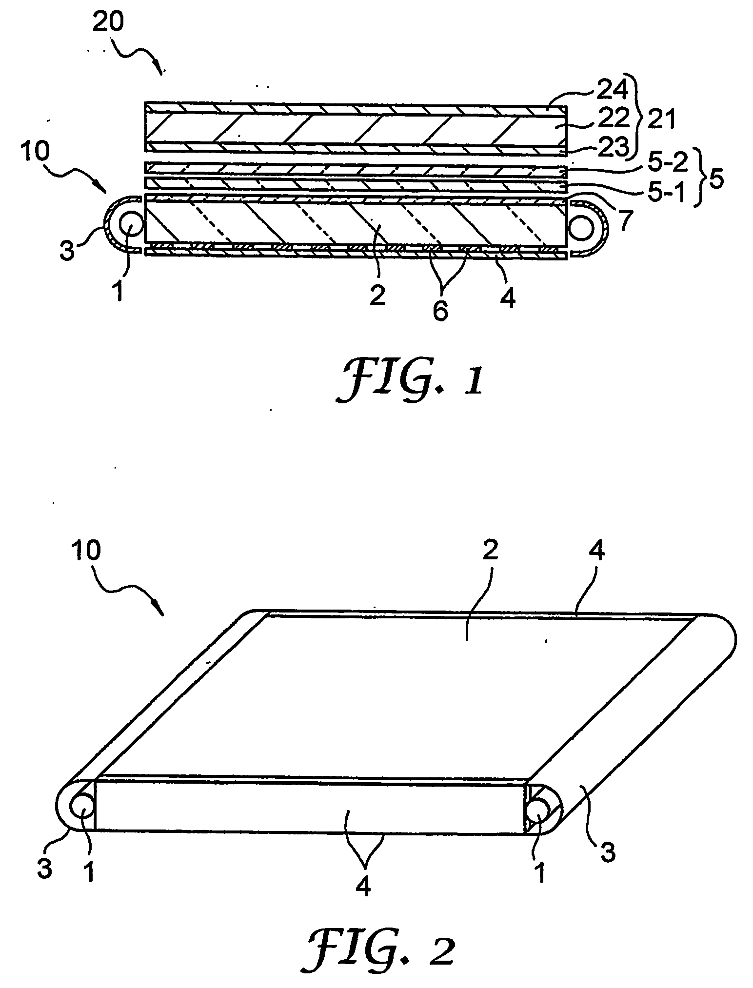
[0116]FIG. 1 is a sectional view schematically showing a transmission type liquid crystal display device according to an embodiment of the invention and FIG. 2 is a perspective view of a backlight illumination unit used as a back surface light source in the liquid crystal display device shown in FIG. 1.

[0117] As shown in FIG. 1, the liquid crystal display device 20 has a liquid crystal panel 21 including a liquid crystal cell 22 and polarization plates 23 and 24 sandwiching from above and below the liquid crystal cell 22. An illumination apparatus of the invention comprising a backlight illumination unit 10 disposed on the side of a non-display surface of the liquid crystal panel 21 ...


PUM


Abstract

To provide an optical film structure useful in a liquid crystal display device and capable of using thin optical films without warp and distortion. An optical film structure comprises at least one optical film, at least four film fixing parts arranged at an outer peripheral portion of the optical film, a film tension controlling member fitted at one of the ends thereof to each of the film fixing parts in such a fashion as to be capable of pulling the optical film under tension while maintaining flatness of the optical film, and a film fixing frame to which the other end of the film tension controlling member is connected and which fixes the optical film.

Description

[0001] This invention relates to an optical film structure, an illumination apparatus and a liquid crystal display device. More particularly, the invention relates to an optical film structure that can be advantageously used in a liquid crystal display device in combination with an illumination unit having at least one optical film, and an illumination apparatus and a liquid crystal display device each having such an optical film structure. In the liquid crystal display device according to the invention, an outer periphery of the optical film, in particular, is fitted to a fixing flame through a film tension controlling member including a flexible member such as a spring or rubber. Therefore, distortion of the optical film due to heat and aging can be absorbed, the surface can be kept flat and consequently, degradation of display performance of the liquid crystal display device can be prevented. BACKGROUND [0002] A liquid crystal display device has features of a small thickness, a s...

Claims


Application Information

Patent Timeline
IPC IPC(8): F21V7/04
CPCG02B6/005G02B6/0068G02B6/0071G02B6/0088G02F1/133608G02F2201/54
Inventor KIDA, AKIRA
Owner 3M INNOVATIVE PROPERTIES CO
Learn More