Method and device for monitoring status of mechanical equipment and abnormality diagnosing device

a technology for mechanical equipment and monitoring status, applied in the direction of machines/engines, nuclear elements, instruments, etc., can solve the problems of large upkeep cost required for maintaining, managing, fracture or wear of teeth,

Inactive Publication Date: 2006-07-27
NSK LTD
View PDF6 Cites 73 Cited by
  • Summary
  • Abstract
  • Description
  • Claims
  • Application Information

AI Technical Summary

Benefits of technology

[0045] (10) An abnormality diagnosis system according to any one of (1) to (9), wherein the comparing / deciding portion makes the abnormality diagnosis of the bearing unit by comparing levels of a frequency due to the abnormality and its higher harmonics with a reference value.
[0046] (11) An abnormality diagnosis system according to any one of (1) to (10), wherein the comparing / deciding portion decides that the abnormality is generated when at least one of peak values of the frequency due to the abnormal and its higher harmonics is larger than a predetermined reference value.
[0047] (12) An abnormality diagnosis system according to any one of (1) to (11), wherein the comparing / deciding portion estimates a degree of damage of the bearing unit based on the peak values of the frequency due to the abnormal and its higher harmonics.
[0048] (13) An abnormality diagnosis system according to any one of (1) to (12), wherein the comparing / deciding portion makes the abnormality diagnosis by comparing the levels of the frequency due to the abnormal and its higher harmonics.

Problems solved by technology

As major defects that are found by the inspection, in the case of the bearing unit, there are the indentation due to the capture of the foreign matter, etc., the flaking due to the rolling contact fatigue, other wear, and others.
Also, in the case of the gear, there are the fracture or wear of the teeth, or the like.
However, in the method of decomposing the overall machinery facility and inspecting the failure with the eye of the person in charge, a decomposing operation of removing the rotating body or the sliding member from the machinery facility and a fitting operation of fitting again the inspected rotating body or sliding member into the machinery facility require much time and labor.
Thus, such a problem existed that a substantial increase in an upkeep cost required for maintaining, managing, or the like the machinery facility is brought upon.
It is the existing circumstances of maintaining / managing operations of the windmill that the person in charge of the maintenance goes to the installation location of the windmill and then conducts the inspection of rotating parts of the windmill there For this reason, such a problem existed that it take an enormous time and cost to maintain / manage the windmill and thus a maintenance efficiency is poor.
Also, it is possible that the inspection itself causes the defect of the rotating body or the sliding member.
Also, since the person in charge of the inspection must check a number of bearings with the eye within a limited time, there existed the problem that such a possibility still remains that such person fails to find the defect.
In addition, since a decision level of the defect varies between individuals and thus exchange of the parts is carried out even though the defect is not found substantially, the above inspection entails a useless cost.
However, in the case where the sensor is fitted onto the body of the vehicle, an SN ratio of the sensed signal from the sensor is worsened because the sensor is provided away from the bearing.
Thus, there existed such a problem that it is difficult to sense / decide the abnormality with high precision.
As a result, there is a possibility of generating the installing error, and the like, and also a lot of man-hours are needed to manage the parts.
Also, it is possible that the outer ring with the hole hinders the sealing performance in the bearing.
In the case where the bearing is used to support the axle of the railway vehicle, it is possible that this diagnosis system decides a great shock generated when the railway vehicle passes over the rail joint as an abnormal signal.
Thus, the abnormality decision may be largely affected.
Thus, the information processing system needs a relatively large installing space and also has a tendency that does not endure the vibration, and the like well.
In addition, this monitoring system becomes large in size.
Therefore, in the case of the machinery facility in which the assurance of the large installing space is difficult, such a problem has arisen that such monitoring system is of little utility.
However, the personal computer that cannot stand up to the external vibration, and the like and is large in size must be separated as far as possible away from the bearing unit, or the like as the vibration generating source.
As a result, the personal computer is apart from the sensor at a predetermined distance or more, and thus it is possible that the problem such as a reduction in a sensing precision due to the influence of the external noise on the information transmission path between the sensor and the personal computer, or the like is caused.

Method used


Image

  • Method and device for monitoring status of mechanical equipment and abnormality diagnosing device
  • Method and device for monitoring status of mechanical equipment and abnormality diagnosing device
  • Method and device for monitoring status of mechanical equipment and abnormality diagnosing device

Examples


first embodiment

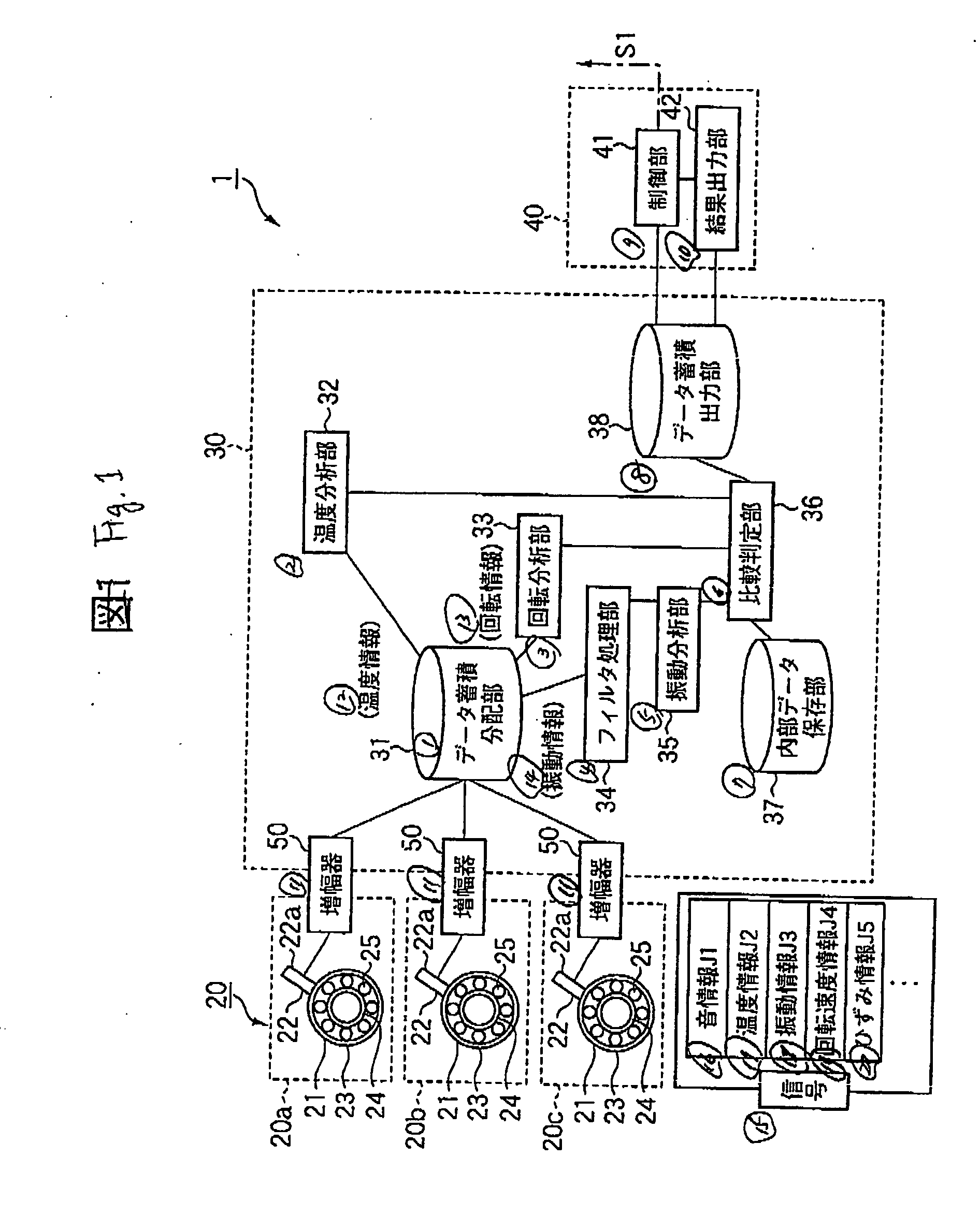
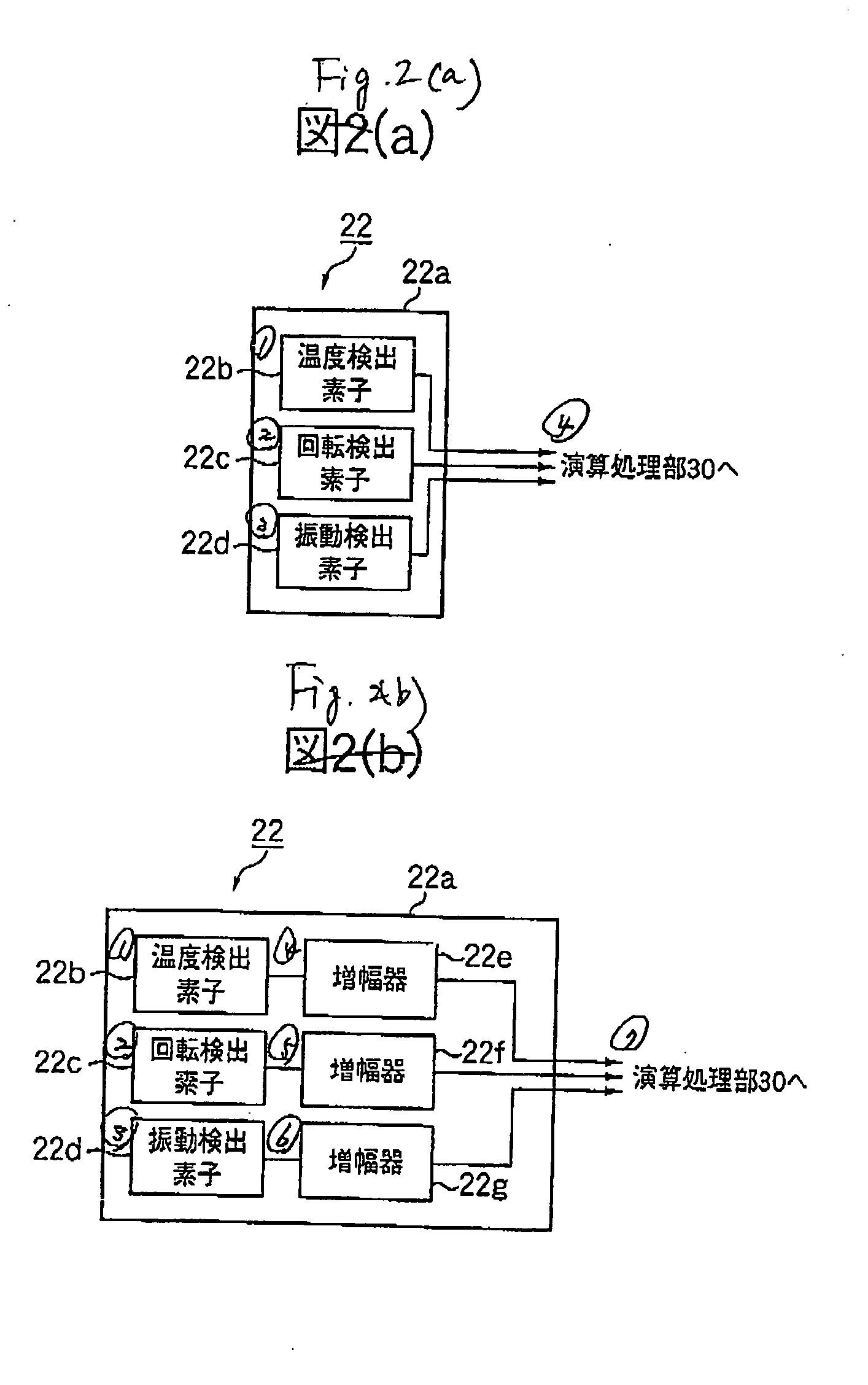
[0182]FIG. 1 shows a railway vehicle abnormality diagnosis system according to a first embodiment of the present invention. An abnormality diagnosis system 1 includes a sensing / processing portion 20 having sensor units 22 each provided to each row of a rolling bearing 21 to output a condition of each row as an electric signal, a calculating / processing portion 30 for calculating / processing the electric signals output from the sensor units 22 to decide the condition such as defect, abnormality, or the like of a railway vehicle facility 10, and a controlling / processing portion 40 for controlling and outputting the decided result of the calculating / processing portion 30.

[0183] The abnormality diagnosis system 1 senses the generation of the abnormality due to the wear or the failure of a plurality of rolling bearings 21 in the bearing unit that bears the axle of the railway vehicle. Each rolling bearing 21 has an outer ring 23 as a stationary portion that is fitted into the vehicle body...

second embodiment

[0279] Next, a machinery facility abnormality diagnosis system according to a second embodiment of the present invention will be explained in detail hereunder. In this case, the same reference symbols are affixed to the portions similar to those in the first embodiment, and thus their redundant explanations will be omitted or simplified hereunder.

[0280] In the present embodiment, as shown in FIG. 27, a sensing / processing portion 51 consisting of sensing portions 51a, 51b, 51c each having a sensor unit 52 that communicates with the calculating / processing portion 30 via radio is provided in place of the sensing / processing portion 20. The sensing portions 51a, 51b, Sic are constructed by fitting the sensor unit 52 onto the outer ring 23 of the bearing 21 respectively. In the sensor unit 52, a temperature sensing element 52b, a rotation sensing element 52c, a vibration sensing element 52d, and a transmitting portion 52h for radio communication are fitted into an interior of a sensor ca...

third embodiment

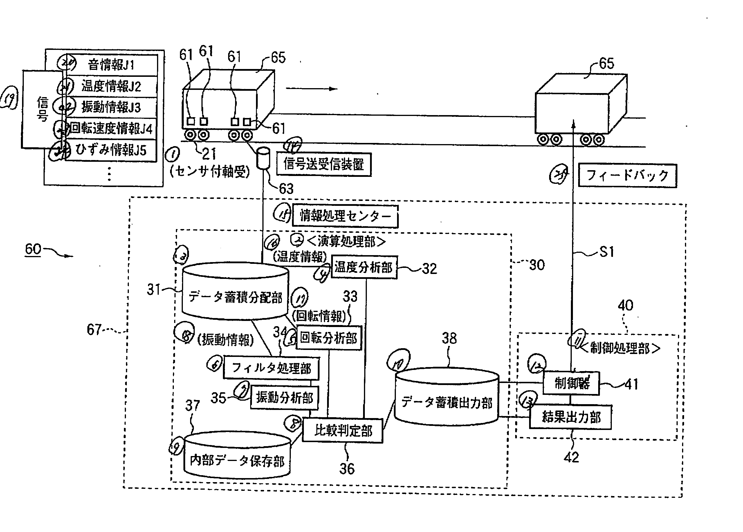
[0283]FIG. 28 is a block diagram showing a schematic configuration of a machinery facility abnormality diagnosis system according to a third embodiment of the present invention. In a rotating body abnormality diagnosis system 60, the sensor unit installed into the sensor built-in bearing 21 that bears the axle is improved in the abnormality diagnosis system 1 in the first embodiment, and also a installing mode of the calculating / processing portion 30 and the controlling / processing portion 40, which execute predetermined processes based on the output signal of the sensor unit, are devised.

[0284] The particular configurations of the processing methods of the calculating / processing portion 30 and the controlling / processing portion 40 are similar to those in the first embodiment. Therefore, the same reference numbers are affixed to the common configurations, and thus explanation of the calculating / processing portion 30 and the controlling / processing portion 40 will be omitted herein.

[...


PUM


Abstract

An abnormality diagnosis system for diagnosing a presence or absence of an abnormality of a bearing unit for a railway vehicle axle, comprises a sensing/processing portion for outputting a signal generated from the bearing unit as an electric signal, a calculating/processing portion for making an abnormality diagnosis of the bearing unit based on an output of the sensing/processing portion, a result outputting portion for outputting a decision result of the calculating/processing portion, and a controlling/processing portion for feeding back a control signal to a control system of the railway vehicle based on the decision result.

Description

TECHNICAL FIELD [0001] The present invention relates to a machinery facility condition monitoring method and system and an abnormality diagnosis system and, more particularly, a machinery facility condition monitoring method and system and an abnormality diagnosis system capable of monitoring conditions such as an abnormality, and so forth in a machinery facility such as a railway vehicle facility, a machine tool, a windmill, a reduction gear, an electric motor, or the like including at least one of a rotating body and a sliding member such as a rolling bearing, a sliding bearing, a ball screw, a linear guide, a linear ball bearing, and the like without decomposition of the machinery facility. BACKGROUND ART [0002] In the prior art, in order to prevent generation of the failure due to the wear or the failure of the rotating body or the sliding member, a thorough overhaul and a visual inspection are applied periodically to the machinery facility such as the railway vehicle facility, ...

Claims


Application Information

Patent Timeline
Patent Type & Authority Applications(United States)
IPC IPC(8): G06F11/30B61F15/20B61K9/04F16C19/52G01M17/10
CPCB61F15/20B61K9/04F03D11/0008F05B2260/80F16C19/52G01M13/045G01M17/10G01N2291/02881G01N2291/2696Y02E10/722F16C19/386F03D80/70F16C2326/10F16C2360/31Y02E10/72
Inventor MIYASAKA, TAKANORIARAMAKI, HIROTOSHIMUTOU, YASUSHISAHARA, JUNTARO
Owner NSK LTD
Why Eureka
Try Eureka