
Apparatus and method for supporting a memeber and controlling flow

a technology of apparatus and member, applied in the direction of valve details, valve arrangement, operating means/releasing devices, etc., can solve the problems of spud having a reduced cross-sectional surface area pilot operated solenoid valve has several limitations, and reduces so as to increase the surface area and reduce the risk of sealing cutting and/or abraded seal

Inactive Publication Date: 2006-07-27
QUANTUM FUEL SYST TECH WORLDWIDE INC
View PDF9 Cites 12 Cited by
  • Summary
  • Abstract
  • Description
  • Claims
  • Application Information

AI Technical Summary

Benefits of technology

[0011] The above limitations are overcome through the use of a material that provides sufficient support for a member yet allows the passage of a fluid. As an example, the material can be a porous metal. The porous metal can be placed in an annular passageway so as to be closely aligned with the passageway's opening. The placement of the porous metal at or near the opening allows the seal to rest not only on the annular cross-section of the passageway, but also on the support provided by the porous metal. This increases the surface area upon which the seal can rest and be supported. The increase in surface area, in turn, reduces the risk that the seal will be cut and / or abraded, particularly in high pressure environments.
[0012] Furthermore, the increase in surface area is obtained without altering the dimensions of the annular passageway. This is particularly advantageous in high pressure environments, where a dimensional alteration may dramatically increase the load on the armature. With the use of the porous metal, there is no need to increase the external diameter of the passageway, thereby avoiding any increase in the load on the armature. In other words, the external diameter of the passageway can be maintained at a minimal size without fear that the seal will be cut and / or abraded during operation.
[0013] Nor is there a need to make costly alterations to the flow of the system to increase the cross-sectional surface area upon which the seal rests. For example, the cross-sectional surface area can be increased by reducing the internal diameter of the annular passageway vis-à-vis the external diameter. While the overall size of the passageway does not change (because the external diameter has not been changed), the reduced internal diameter of the passageway changes the flow rate through the passageway. This may require changing the bleed rates of other passageways in the whole system. However, the use of porous metal provides an increase in surface area without dramatically altering the flow of the fluid through the passageway or allowing the flow of the fluid to be altered as desired. The porosity of the metal allows the fluid to flow through the passageway in any manner dictated by the apparatus, system or operation.
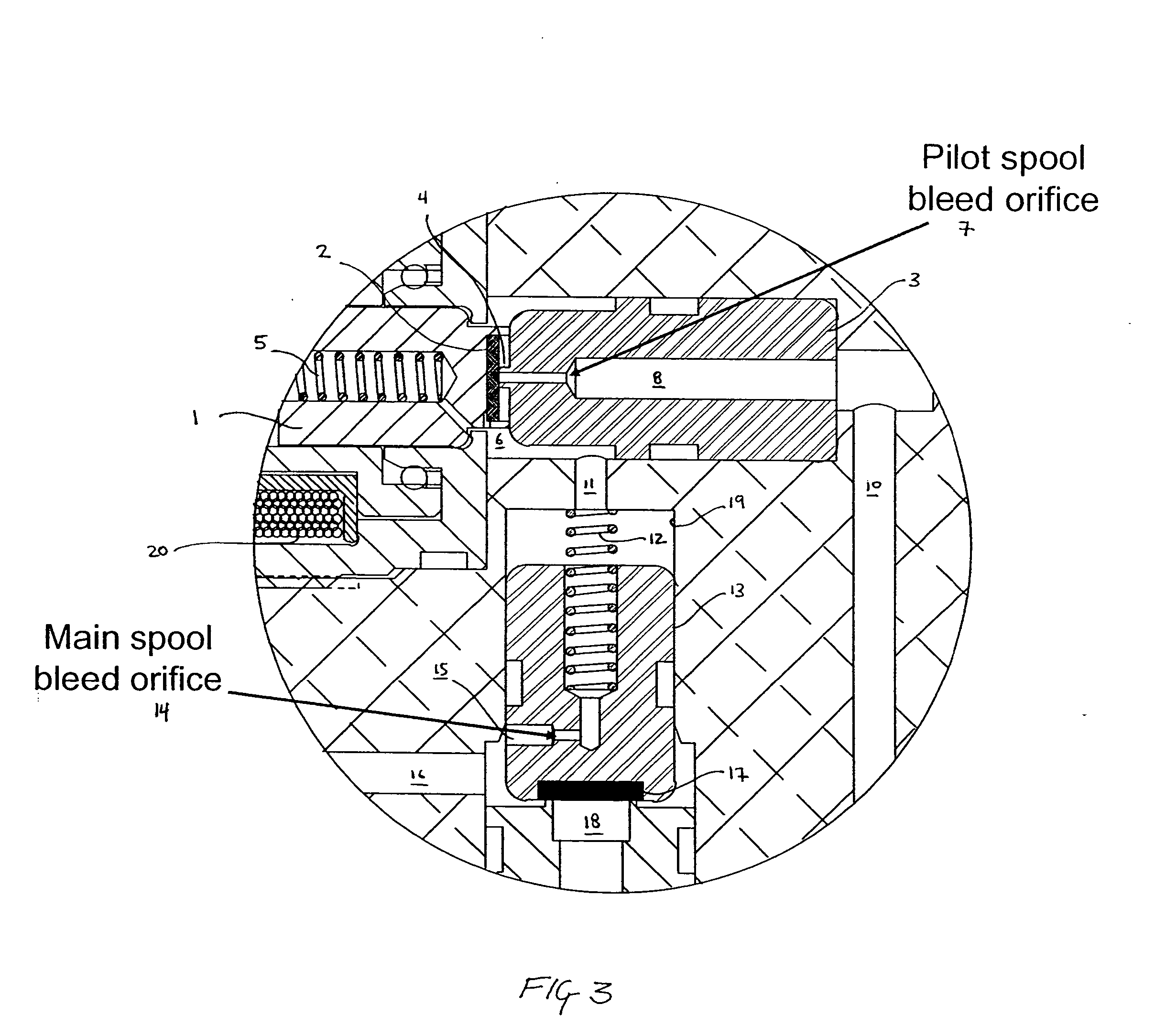
[0014] Indeed, an additional feature of the present invention is that the placement of a porous metal in the passageway provides design control over the flow of the fluid in the passageway and, if desired, through the whole system. For example, two metals of different porosity can be placed in the pilot spool bleed passageway and a main spool bleed passageway, respectively. The difference in porosity can be used to establish and maintain the correct relationship between the flow rates of the two passageways. In this manner, it is not necessary to exercise close tolerance control over the passageways, because the porous metals provide the correct relationship.

Problems solved by technology

The pilot operated solenoid valve has several limitations, particularly in a high pressure environment such as 10,000 psi.
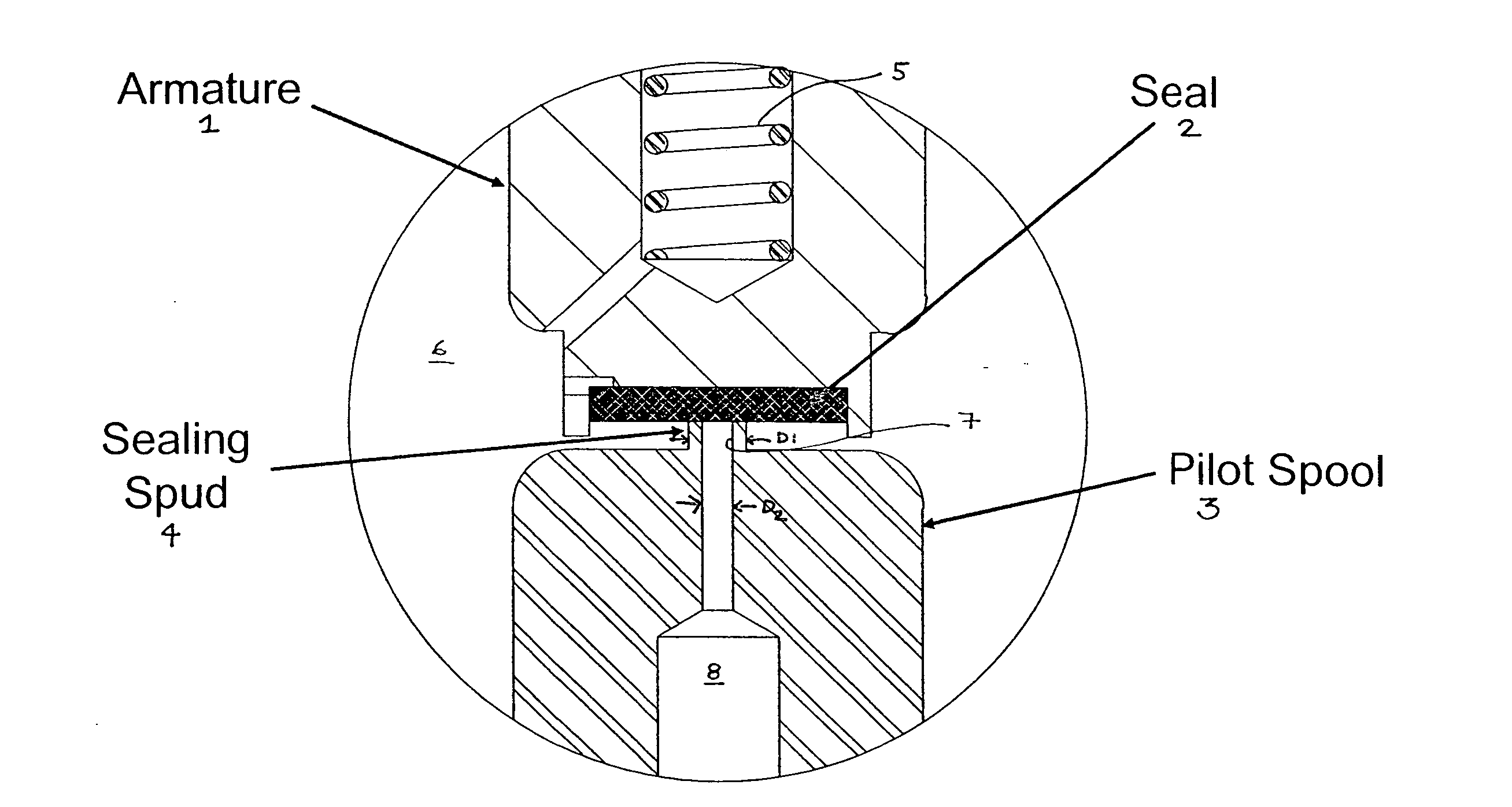
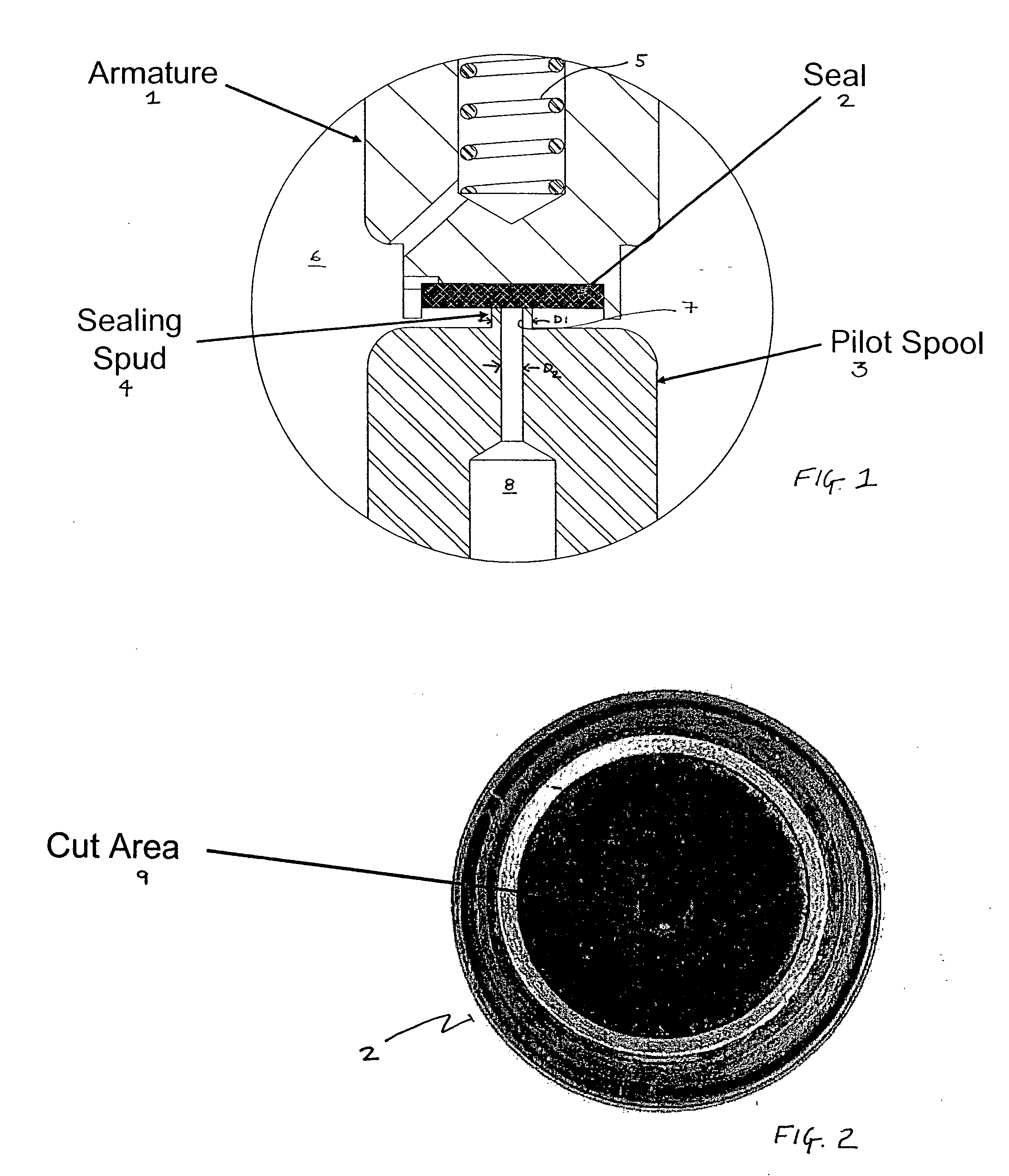
First, a high pressure environment requires the external diameter D1 of the sealing spud to be fully minimized, otherwise the load on the armature 1 will be too large.
It has been discovered that a sealing spud having a reduced cross-sectional surface area will cut and / or abrade the seal during operation, particularly in a high pressure environment.
A second limitation of a pilot operated solenoid valve is sizing the pilot spool orifice vis-à-vis the main spool orifice to ensure proper operation. FIG. 3 illustrates an expanded detailed view of the pilot-operated solenoid valve of FIG. 1.
Such close tolerance control increases costs and is prone to manufacturing error.

Method used


Image

  • Apparatus and method for supporting a memeber and controlling flow
  • Apparatus and method for supporting a memeber and controlling flow
  • Apparatus and method for supporting a memeber and controlling flow

Examples


Embodiment Construction

[0027]FIG. 4 illustrates an apparatus for regulating a fluid. The apparatus comprises a body 108. Extending from the surface of body 108 is an annular extension 106. A passageway 114 extends from the top surface 106a of the annular extension 106 through the body 108 to communicate with a larger passageway 116. It should be noted that annular extension 106 is not necessary. The surface of body 108 can be flush with an opening for passageway 114.

[0028] The apparatus further comprises a material 112 placed within the entire internal cross-section of passageway 114. The material is placed in passageway 114 such that the material is closely aligned with the top surface 106a of the annular extension 106. It can be flush with the top surface 106a of the annular extension 106 or at a distance from the top surface 106a. The material 112 is further placed to extend through passageway 114 and into passageway 116.

[0029] Material 112 provides support for a member 104 (such as a seal) while all...


PUM


Abstract

A material is used in an apparatus that regulates a fluid to provide sufficient support for a member, such as a seal, yet allow the passage of the fluid in a passageway. The material can be a porous metal which is placed in the passageway so as to be closely aligned with the passageway's opening. The placement of the porous metal at or near the opening allows the seal to rest on the cross-section of the passageway as well as on the support provided by the porous metal. The increase in surface area upon which the seal is support reduces the risk that the seal will be cut and / or abraded, particularly in high pressure environments. The use of the material is the passageway further provides design control over the flow of the fluid.

Description

CROSS REFERENCE TO RELATED APPLICATION [0001] The present invention claims the benefit under 35 USC 119(e) of U.S. Provisional Application Ser. No. 60 / 642,796 filed Jan. 10, 2005, the contents of which are incorporated by reference herein.BACKGROUND OF THE INVENTION [0002] The present invention relates to an apparatus and method for supporting a member and, additionally, controlling a flow of a fluid. [0003]FIG. 1 illustrates a detailed view of a conventional pilot operated solenoid valve. The detailed view illustrates the arrangement between the armature 1 and the pilot spool 3. The pilot spool 3 has a passageway 7 for bleeding a gas away from the main spool (which is not illustrated in FIG. 1) through passageway 8. Passageway 7 includes a short extension, known as a sealing spud 4, beyond the top surface of the pilot spool 3. The sealing spud has an annular cross-section defined by the internal diameter D2 of passageway 7 and the external diameter D1 of sealing spud 4. Seal 2 rest...

Claims


Application Information

Patent Timeline
IPC IPC(8): F16K25/00
CPCF16K1/34F16K1/52F16K25/00F16K25/005F16K31/406
Inventor GALLAGHER, PAULSTAPLES, HAROLD ANTHONY IIIMILLER, ROBERT
Owner QUANTUM FUEL SYST TECH WORLDWIDE INC
Learn More