
Hook style tamper evident lid

a lid and lid technology, applied in the field of injection moulded containers, can solve the problems of removing all visual evidence of the release of the locking ribs, requiring expensive moulds for the container and the lid, and reducing the service life of the lid, so as to facilitate the tearing of the rim

Inactive Publication Date: 2006-07-27
STACKTECK SYST LTD
View PDF16 Cites 41 Cited by
  • Summary
  • Abstract
  • Description
  • Claims
  • Application Information

AI Technical Summary

Benefits of technology

[0008] A tamper evident lid is provided for mounting over an opening of a container having sidewalls with a lip extending outwardly therefrom to define an opening. The lid has a base, a rim extending about the base for receiving the lip and at least one resiliently flexible finger extending radially inwardly from the rim for engaging the lip. Each finger has a length exceeding the distance between an inside of the lip and the sidewall and extends towards the base when the lid is mounted on the container. At least one frangible membrane is formed in the rim and associated with at least one of the fingers for facilitating tearing of the rim to disengage the associated finger(s) from the lip thereby enabling removal of the lid from the container while leaving evidence of removal by way of a torn frangible membrane.
[0021] The rim may be a recess extending from the fingers to the lower edge to accommodate the fingers thereby facilitating stripping of the lid in an injection moulding process.

Problems solved by technology

Unfortunately, packages having tamper evident features generally require specific container and lid designs making the container and the lid a unique combination.
A disadvantage to this type of design is that expensive moulds are required not only for the container but for the lid and the moulds are often limited in design to a single product.
If special containers and lids are to be used, it may be necessary to install additional machinery in a filling line to accommodate assembly limitations caused by the special tamper evident containers.
However, one disadvantage of Rathbun's lid is that the locking ribs are completely removed from the lid once the lid is initially from the container, thus removing all visual evidence of the released locking ribs.

Method used


Image

  • Hook style tamper evident lid
  • Hook style tamper evident lid
  • Hook style tamper evident lid

Examples


Embodiment Construction

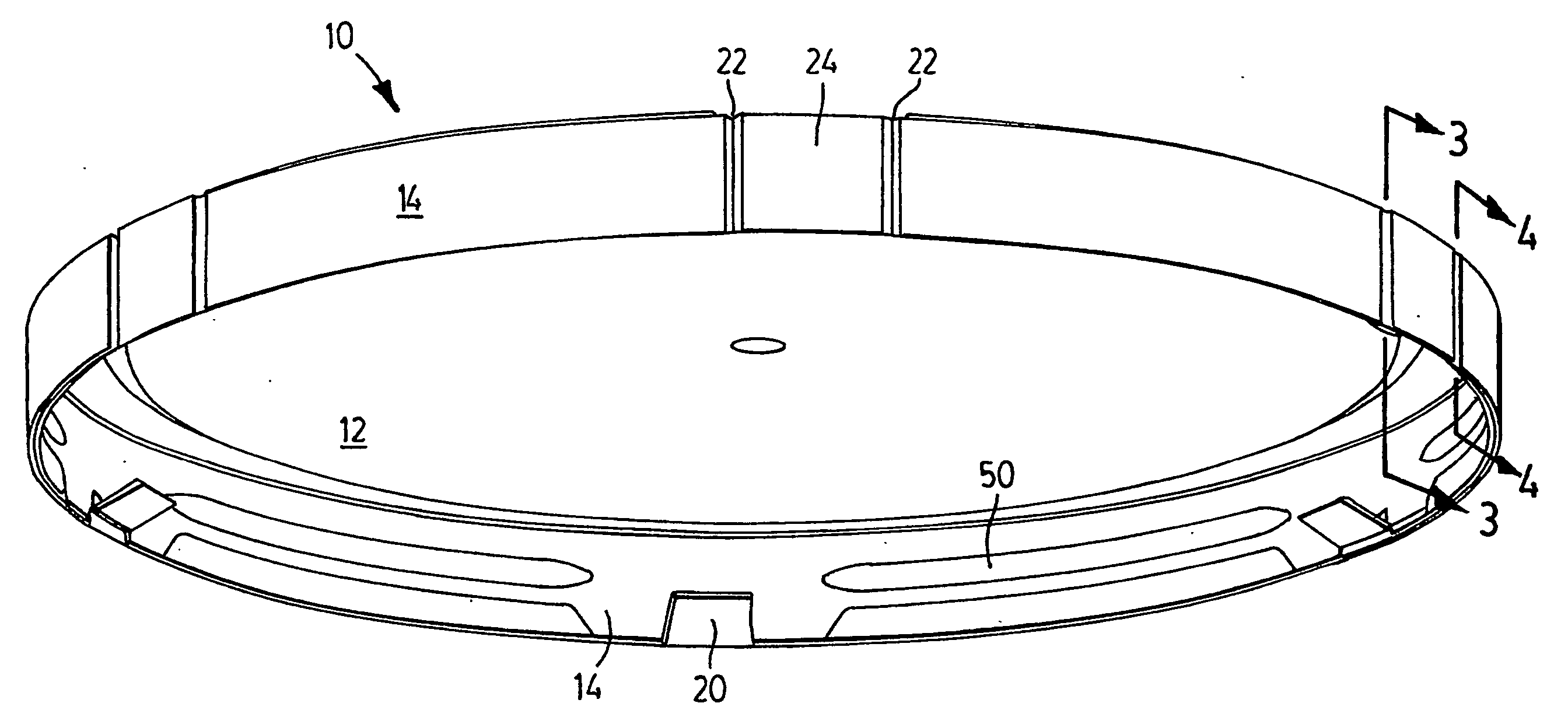
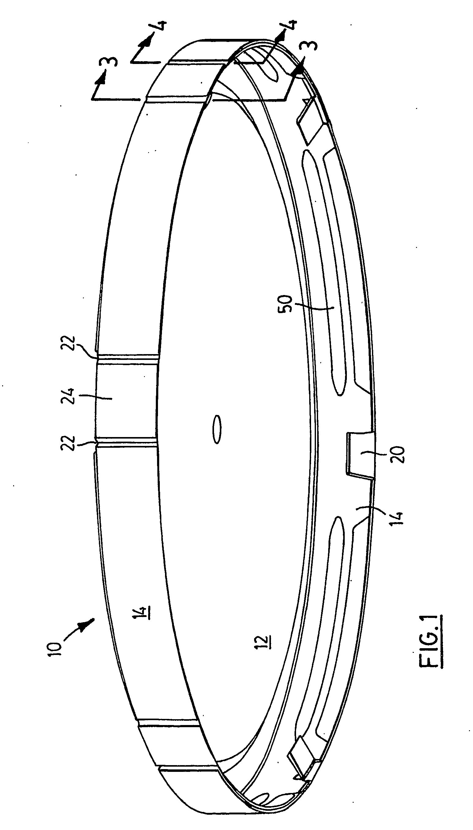
[0053] A tamper evident lid (“lid”) according to the present invention is generally illustrated by reference 10 in the accompanying illustrations. The lid 10 has a base 12 and a rim 14 which extends about the perimeter of the base 12.

[0054] Discrete fingers 20 extend from an inside of the rim 14. The fingers extend radially inwardly and toward the base 12 (inwardly and upwardly as illustrated in the figures).

[0055] The lid 10 is intended for mounting over a “standard container”13 as illustrated in FIG. 5. A portion of a sidewall of such a container 13 is shown in dashed lines at reference 30. As typical with such containers 13 which are commonly used for food and other applications, the sidewall 30 terminates in an outwardly and downwardly extending lip 32. The lip 32 defines an opening 34 over which the lid 10 may be mounted.

[0056] Each of the fingers 20 has a length which exceeds the distance or “gap” between the inside of the rim 14 and the outside of the sidewall 30 as illust...


PUM

PropertyMeasurementUnit
Lengthaaaaaaaaaa
Thicknessaaaaaaaaaa
Areaaaaaaaaaaa

Abstract

A tamper evident lid is provided for mounting over an opening of a container having sidewalls with a lip extending outwardly therefrom to define the opening. The lid has a base, a rim extending about a perimeter of the base for receiving the lip and at least one finger extending upwardly from the rim and toward the base for engaging an underside of the lip. A frangible membrane is associated with the fingers to facilitate outward tearing of the finger regions away from the sidewalls. Each finger has a length exceeding the distance between an inside of the lip and the sidewall.

Description

[0001] This application is a continuation-in-part of International Application No. PCT / CA03 / 00055, filed Jan. 17, 2003, and also a continuation-in-part of International Application No. PCT / CA02 / 01311, filed on Aug. 26, 2002, and also claims the benefit of U.S. Provisional Application No. 60 / 399,731, filed Aug. 1, 2002.FIELD OF THE INVENTION [0002] This invention relates generally to injection moulded containers and their lids. More specifically this invention relates to tamper evident lids which may be applied to standard containers. BACKGROUND OF THE INVENTION [0003] Tamper evident (TE) features are very important in the packaging industry. Unfortunately, packages having tamper evident features generally require specific container and lid designs making the container and the lid a unique combination. A disadvantage to this type of design is that expensive moulds are required not only for the container but for the lid and the moulds are often limited in design to a single product. [...

Claims


Application Information

Patent Timeline
IPC IPC(8): B65D41/16B65D41/32B29C45/00B29C45/44B65D43/02
CPCB29C45/0081B29C45/4407B29L2031/565B65D41/3423B65D43/0262B65D2101/003B65D2543/00092B65D2543/00194B65D2543/00296B65D2543/00379B65D2543/00527B65D2543/00537B65D2543/00629B65D2543/00657B65D2543/00685B65D2543/00694B65D2543/00759B65D2543/00768B65D2543/00796B65D2543/00805B65D2401/20
Inventor DE CANDIDO, RICK
Owner STACKTECK SYST LTD
Learn More