Composite fabrication facility of steel tube and fabrication method of steel tube

a technology of composite fabrication and fabrication method, which is applied in the direction of manufacturing tools, other domestic articles, manufacturing equipment/tools, etc., can solve the problems of gas leakage in the piping, process is not easy to carry out, and the surrounding is prone to sparks, etc., and achieves the effect of small size and easy movemen

Inactive Publication Date: 2006-07-27
OGAWA KIYOSHI
View PDF2 Cites 14 Cited by
  • Summary
  • Abstract
  • Description
  • Claims
  • Application Information

AI Technical Summary

Benefits of technology

[0014] The present invention has been made in order to solve the conventional problems described above. It is an object of the present invention to provide a combined machining equipment for steel tubes which is capable of not only flaring a steel tube, but also grinding a flared surface of the steel tube, grooving an end of the steel tube, and peeling a lining off the steel tube, and which is small in size and can easily be moved.

Problems solved by technology

Therefore, the worker needs to take improper postures to weld the entire circumferential surfaces of the tubes, tending to introduce welding irregularities and misalignments and also to cause a spark-induced risk to surroundings.
Such a process is not easy to carry out.
However, because the flanges need to be welded to the steel tubes in advance, if the flanges are not welded with sufficient accuracy, then a liquid or gas leakage may occur in the piping, or the piping may not be laid in a desired layout.
When such steel tubes are flared, the zinc layer is peeled off or pressed and deformed into surface irregularities under the pressing and squeezing forces, resulting in a reduction in the sealing capability of the joined surfaces.
However, the conventional flanging apparatus for flaring steel tubes is large and heavy because it is necessary to move the single-stage machining head and the dual-stage machining head to respective positions in front of fixed steel tubes, and hence cannot easily be brought into piping construction sites.
At a piping construction site, since steel tubes are manually grooved, a long period of time is required to machine the steel tubes and the steel tubes are liable to have an irregular finish.
However, since this combined machining equipment is heavy and cannot easily be moved, it is not easy to use the combined machining equipment on site.

Method used


Image

  • Composite fabrication facility of steel tube and fabrication method of steel tube
  • Composite fabrication facility of steel tube and fabrication method of steel tube
  • Composite fabrication facility of steel tube and fabrication method of steel tube

Examples


first embodiment

[0054] A flaring process that is performed using the combined machining equipment for steel tubes according to the present invention will be described below with reference to the drawings.

[0055] First, clamp chuck 151 that matches the dimensions of steel tube 110 to be machined is installed on steel tube holding apparatus 102.

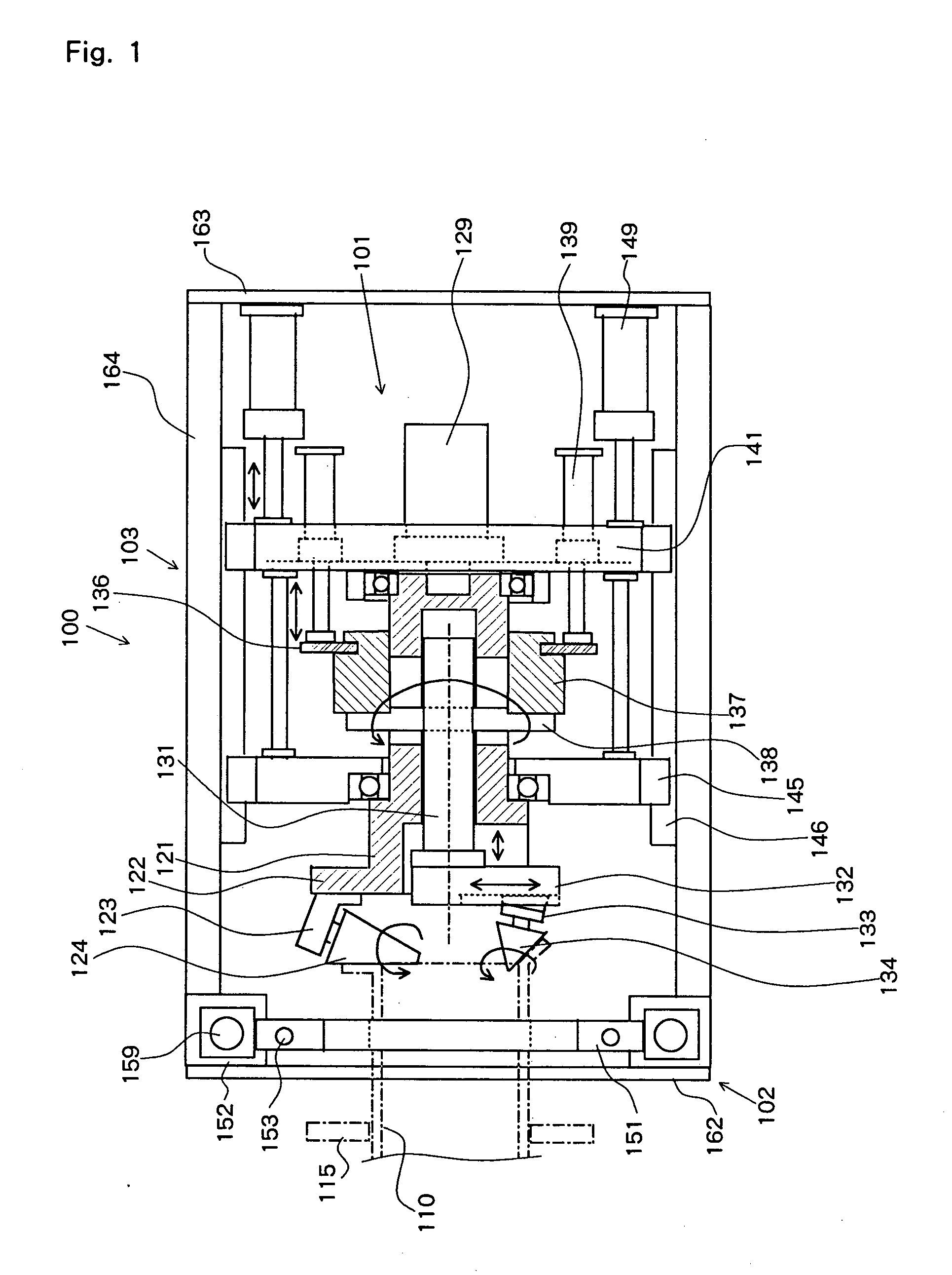
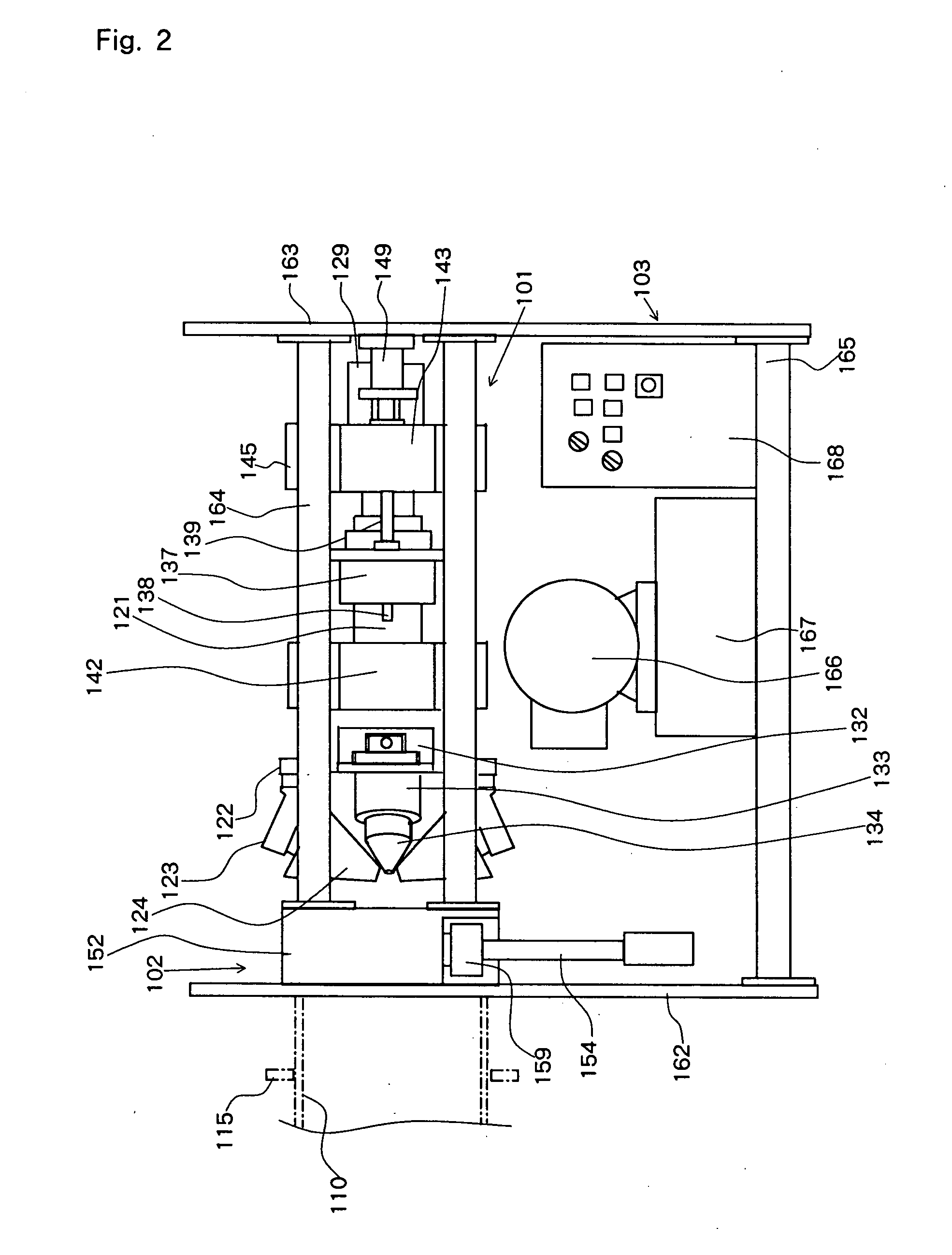
[0056] With auxiliary shaft 131 fully retracted with respect to main shaft 121, slide screw nuts 172 on the lower surface of first machining head units 133 are moved by slide screws 171 on first machining head mount base 132. First machining heads 134 are set to a position corresponding to the diameter of steel tube 110, and then fixed in that position by fixing screws 173 (see FIGS. 6A and 6B).

[0057] Main shaft 121 is moved forwardly to a predetermined machining start position, and steel tube 110 is inserted into clamp chuck 151. When the tip end of steel tube 110 is brought into contact with second machining heads 124, first hydraulic cylinders 159 are actu...

second embodiment

[0061] The flaring process will be described in detail in combination with a flared surface grinding step with reference to a flowchart of FIG. 11 to be described below.

[0062] A combined machining equipment for steel tubes according to a second embodiment of the present invention will be described below with reference to FIGS. 7, 10A through to 10C. According to the second embodiment, a flared surface grinding unit is added as an attachment to the first embodiment.

[0063] The combined machining equipment for steel tubes according to the second embodiment has flared surface grinding unit 125 in addition to the combined machining equipment for steel tubes according to the first embodiment. Flared surface grinding unit 125 has flared surface grinding cutter 126 supported on its tip end for grinding the end of steel tube 110 which has been pressed and deformed in the flaring process. Flared surface grinding unit 125 is disposed on flared surface grinding unit mount 194 (see FIGS. 10A-1...


PUM

PropertyMeasurementUnit
angleaaaaaaaaaa
angleaaaaaaaaaa
diameteraaaaaaaaaa

Abstract

The present invention pertains to a combined machining equipment for steel tubes, and a machining method is of a small size, can easily be moved, and is capable of not only flaring a steel tube, but also grinding a flared surface, forming a groove, and peeling off a lining. A main shaft (121) is rotatably mounted on a slide frame (141) slidable with respect to a common mount (103), and a second machining head (124) is mounted on a flange on the distal end of the main shaft (121). An auxiliary shaft (131) is slidably disposed in the main shaft (121) for rotation therewith. A first machining head (134) is mounted on a mount base (132) on the distal end of the auxiliary shaft (131). When the main shaft (121) is rotated and moved back and forth and the auxiliary shaft (131) is moved back and forth with respect to the main shaft (121), the first machining head (134) spreads the tip end of a steel tube (110) held by a steel tube holding apparatus (102) to a first position, and the second machining head (124) spreads the tip end of the steel tube (110) to a predetermined flanged position, thus flaring the tip end of the steel tube (110).

Description

TECHNICAL FIELD [0001] The present invention relates to a combined machining equipment for steel tubes, and more particularly to a combined machining equipment for machining a joint portion of a steel tube for use in piping applications and a method of machining a steel tube. BACKGROUND ART [0002] Steel tubes are widely used as pipes for transporting fluid, and steel tubes that are cut to certain lengths are joined to make up a desired pipe system. According to one process of joining two steel tubes, groves are formed in ends of the steel tubes, the grooved ends are held end to end, and the outer circumferential surfaces of the joined ends are welded to each other. Alternatively, flanges or the like are welded to ends of steel tubes, providing flanged steel tubes, and the flanges are fixed to each other by bolts and nuts on site. According to still another joining process, the outer surfaces of ends of tubes are externally threaded, and are joined to each other by a sleeve coupling ...

Claims


Application Information

Patent Timeline
Patent Type & Authority Applications(United States)
IPC IPC(8): B21D19/04B23K31/00B23P23/04B23Q9/02B24B9/00
CPCB21D19/046B21H7/185B23P23/04B23Q9/02B24B9/007B21D51/16B21D41/02B21D19/04B23P23/02
Inventor OGAWA, KIYOSHI
Owner OGAWA KIYOSHI
Why Eureka
Try Eureka