
Pulsed laser source with adjustable grating compressor

a laser source and compressor technology, applied in the field of pulsed lasers and fabrication of waveguides, can solve the problems of inability to manufacture many waveguide materials using commercial laser systems, complex waveguide writing process, etc., and achieve the effect of optimal pulse compression

Active Publication Date: 2006-07-20
IMRA AMERICA
View PDF23 Cites 65 Cited by
  • Summary
  • Abstract
  • Description
  • Claims
  • Application Information

AI Technical Summary

Benefits of technology

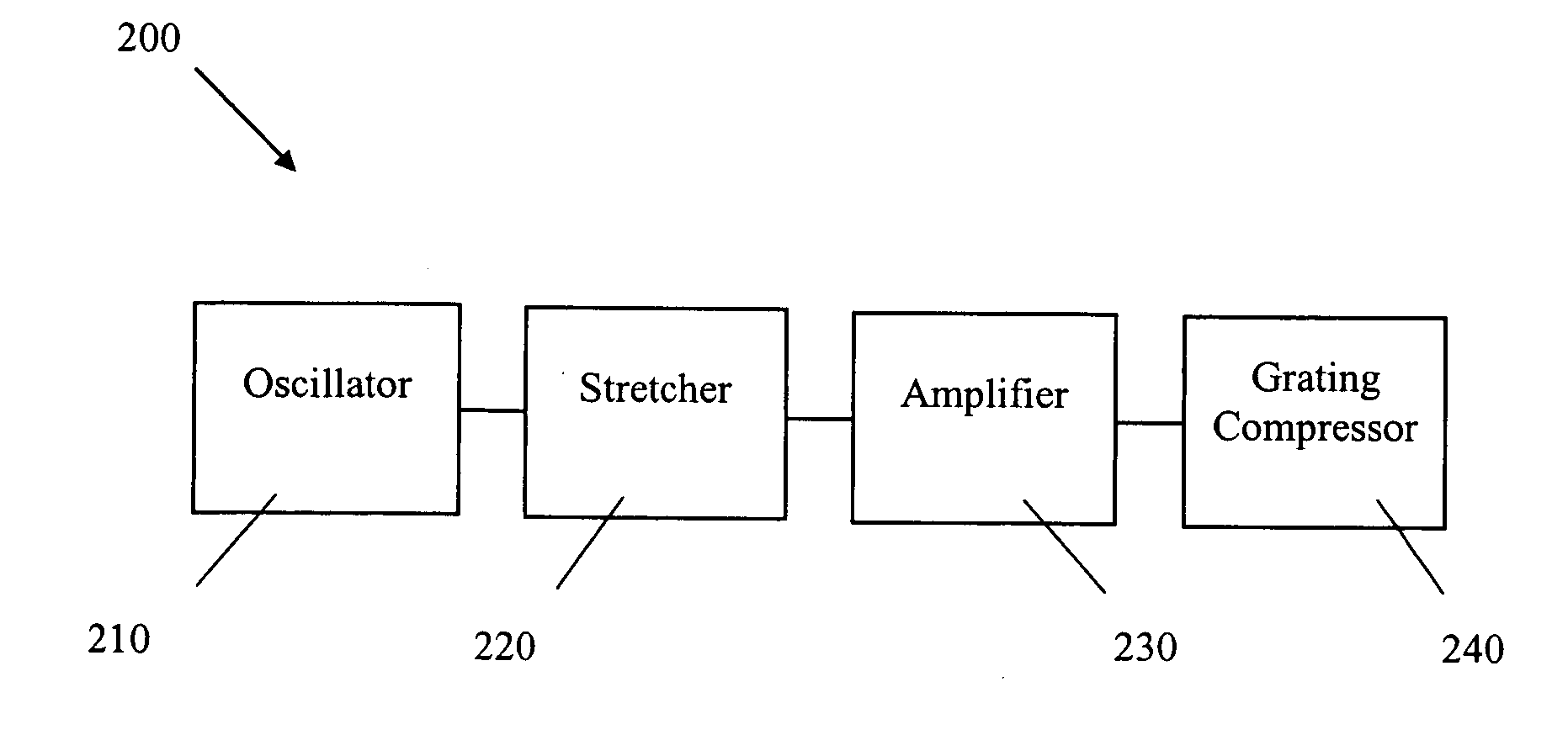
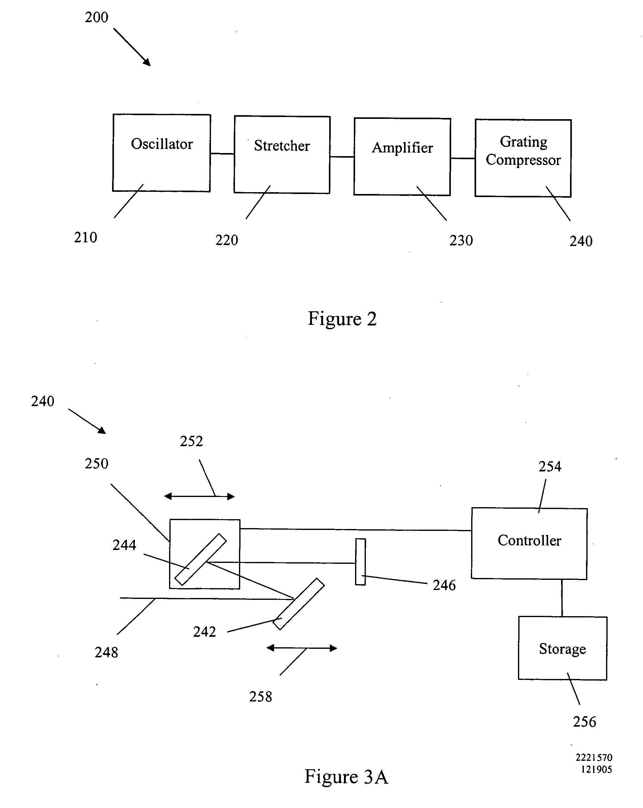
[0033] In another embodiment of this system for fabricating a waveguide, the infrared laser includes a compressor grating and a mechanism by which the dispersion of compressor grating is automatically adjusted to provide optimal pulse compression with changes in the repetition rate.
[0034] Another embodiment of this

Problems solved by technology

Unfortunately, waveguide writing is a complex process.
The process may not be feasible for many waveguide materials using commercially available laser systems.

Method used


Image

  • Pulsed laser source with adjustable grating compressor
  • Pulsed laser source with adjustable grating compressor
  • Pulsed laser source with adjustable grating compressor

Examples


Embodiment Construction

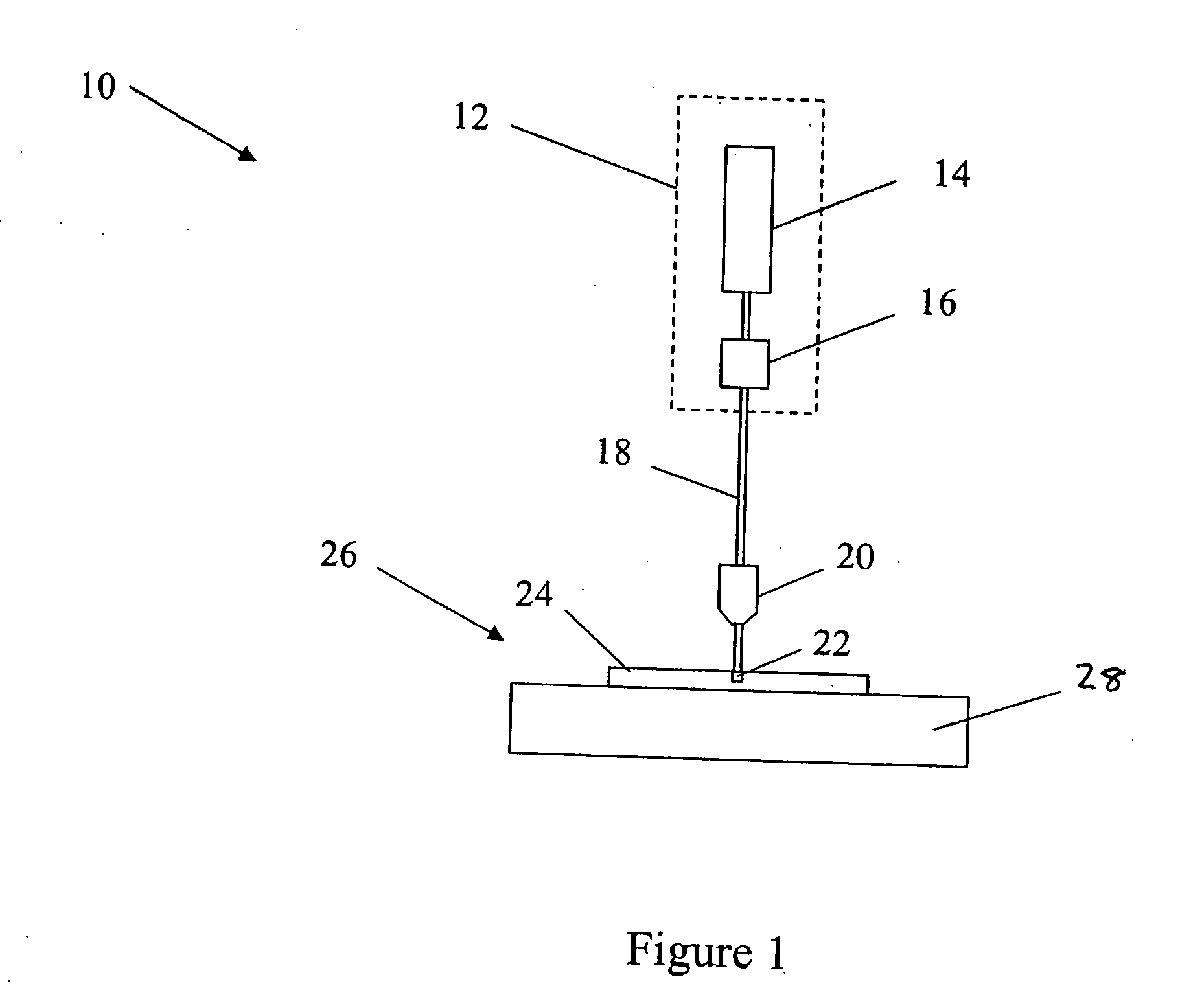
[0042] A system 10 capable of writing a waveguide in a medium comprising fused silica is illustrated in FIG. 1. This system 10 comprises a visible laser light source 12 that outputs visible light. The visible laser light source 12 has an output wavelength in the green region of the visible optical spectrum, e.g., between about 490 and 500 nanometers. This wavelength range may also be between about 450 and 700 nanometers in some embodiments.

[0043] The visible laser light source 12 comprises a Yb-doped fiber laser 14 that outputs light having a wavelength of approximately 1045 nanometers. An exemplary Yb-doped, amplified fiber laser 14 comprises the FCPA μJewel available from IMRA America, Ann Arbor Mich. This fiber laser has a pulse repetition rate between about 100 kHz and 5 MHz and is capable of outputting ultrashort pulses having pulse durations between about 300 fs and 700 fs. The high repetition rate allows the fabrication of low-loss waveguides at relatively high translation s...


PUM

PropertyMeasurementUnit
Lengthaaaaaaaaaa
Dispersion potentialaaaaaaaaaa
Widthaaaaaaaaaa

Abstract

Various embodiments described herein relate to a laser source for producing a pulsed laser beam comprising a plurality of ultrashort optical pulses having a variable repetition rate. In one embodiment, the laser source comprises a fiber oscillator, which outputs optical pulses and a pulse stretcher disposed to receive the optical pulses. The optical pulses have an optical pulse width. The pulse stretcher has dispersion that increases the optical pulse width yielding stretched optical pulses. The laser source further comprises a fiber amplifier disposed to receive the stretched optical pulses. The fiber optical amplifier has gain so as to amplify the stretched optical pulses. The laser source includes an automatically adjustable grating compressor having dispersion that reduces the optical pulse width. The grating compressor automatically adjusts this dispersion for different repetition rates.

Description

PRIORITY APPLICATION [0001] This application claims priority to U.S. Patent Application No. 60 / 638,072 filed Dec. 20, 2004, entitled “OPTICAL WAVEGUIDE WRITING UTILIZING VISIBLE FEMTOSECOND PULSES,” (Attorney Docket No. IMAA.030PR), which is hereby incorporated by reference herein in its entirety.BACKGROUND [0002] 1. Field of the Invention [0003] The apparatus and methods relate to pulsed lasers and to fabricating waveguides with pulsed lasers. [0004] 2. Description of the Related Art [0005] As is well known, waveguides comprise optical pathways for propagating light within a medium such as, for example, within a slab. The waveguide may be fabricated by modifying a refractive index of a material in the medium. Examples of waveguides include channel waveguides that may be disposed at a surface of or buried within a substrate. Integrated optics with complicated 3-D architectures may be formed with such waveguides structures. [0006] Waveguides may be fabricated by shining light into th...

Claims


Application Information

Patent Timeline
IPC IPC(8): H01S3/10H01S3/08
CPCB23K26/0635G02B6/02138H01S3/0057G02B6/02147G02B6/13G02B6/02142B23K26/0624
Inventor SHAH, LAWRENCE
Owner IMRA AMERICA
Learn More