
Substrate type dipole antenna having stable radiation pattern

a dipole antenna and substrate technology, applied in the direction of radiating element structural forms, resonant antennas, elongated active element feeds, etc., can solve the problems of electric feed interference between the antenna and the coaxial cable, and the maximum radiation that the designer originally anticipated is not obtained

Active Publication Date: 2006-07-20
SAMSUNG ELECTRONICS CO LTD
View PDF8 Cites 35 Cited by
  • Summary
  • Abstract
  • Description
  • Claims
  • Application Information

AI Technical Summary

Benefits of technology

[0011] Accordingly, it is an aspect of the present invention to provide a UWB (Ultra WideBand) substrate type dipole antenna, which is capable of preventing leakage of electric current on an outer part of an external conductor of a coaxial cable and subsequently achieving a stabilized radiation pattern.
[0021] The plurality of slits may block the electric current flowing on the second radiators from transmitting to the coaxial cable.
[0027] The plurality of slits may block electric current flowing on the surface of the second radiator from transmitting to the coaxial cable.

Problems solved by technology

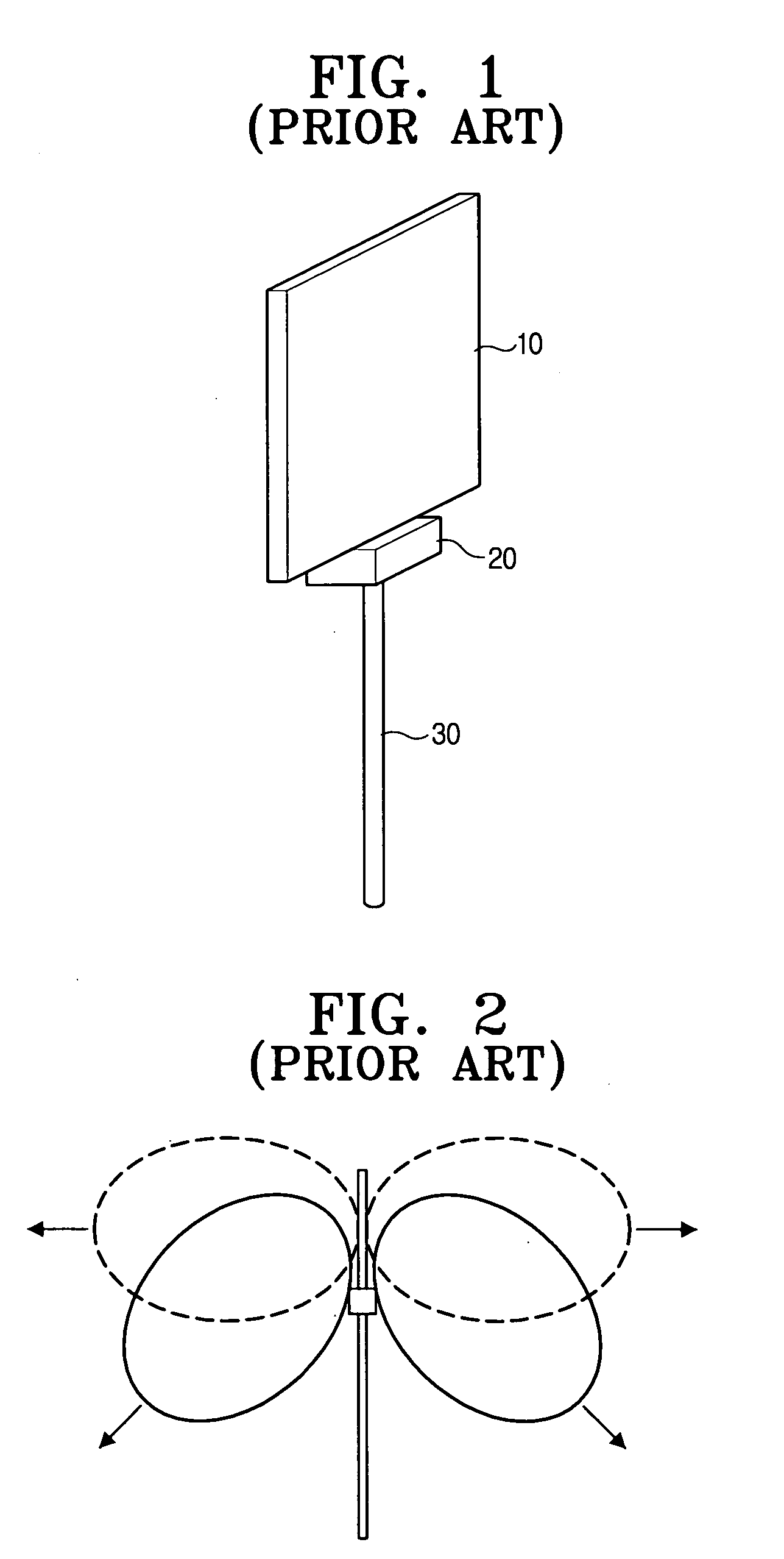
Due to such leakage of electric current, the radiation pattern of the antenna changes, and therefore, the maximum radiation that the designer originally anticipated is not obtained.
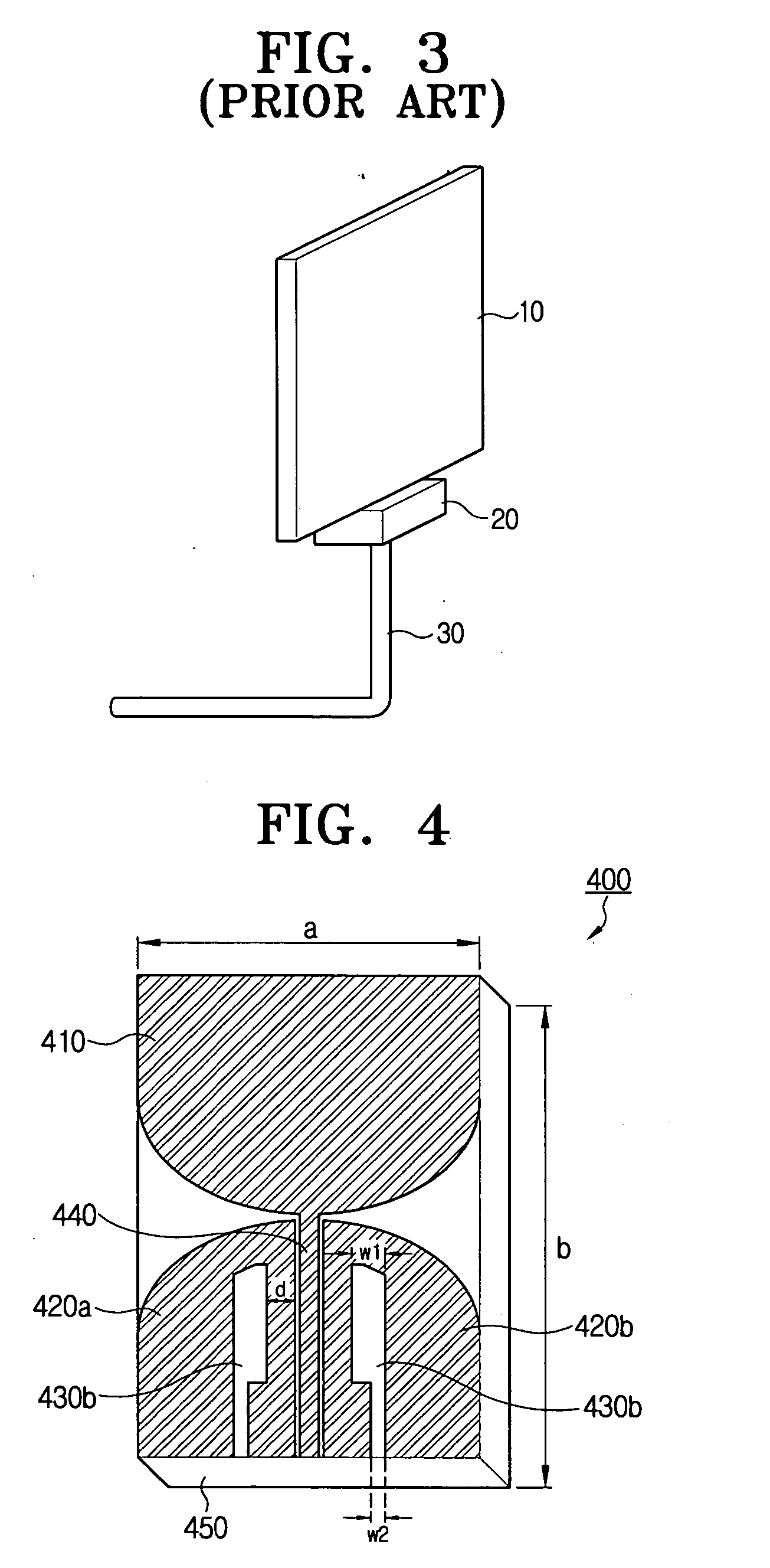
However, this type of electric feed has an interference of electric waves between the antenna and the coaxial cable due to the perpendicular orientation of the coaxial cable with respect to the antenna substrate.

Method used


Image

  • Substrate type dipole antenna having stable radiation pattern
  • Substrate type dipole antenna having stable radiation pattern
  • Substrate type dipole antenna having stable radiation pattern

Examples


Embodiment Construction

[0035] Exemplary embodiments of the present invention will be described herein below with reference to the accompanying drawings.

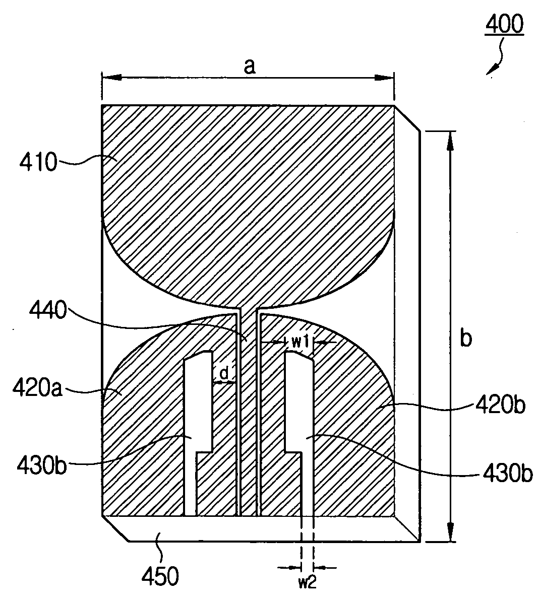
[0036]FIG. 4 is a view illustrating a Ultra WideBand (UWB) substrate type dipole antenna utilizing a coplanar waveguide (CPW) electric feed method according to a first exemplary embodiment of the present invention. Referring to FIG. 4, a UWB substrate type dipole antenna utilizing a CPW electric feed according to the first exemplary embodiment of the present invention includes a dielectric substrate 450, a first radiator 410 formed by coating a conductor on the same upper plane of the dielectric substrate 450, a signal line 440, and a plurality of second radiators 420a and 420b. The first radiator 410, the signal line 440 and the plurality of second radiators 420a and 420b may be formed by coating with a printed circuit board processing technique.

[0037] The first radiator 410, the plurality of second radiators 420a and 420b, and the signal line 440 are f...


PUM


Abstract

A Ultra WideBand (UWB) substrate type dipole antenna is provided which has a stable radiation pattern. The UWB substrate type dipole antenna includes a dielectric substrate, a first radiator formed on a side of the dielectric substrate, a signal line transmitting an energy from a coaxial cable to the first radiator, and a plurality of second radiators formed at a predetermined distance from the first radiator and the signal line, and respectively having therein a plurality of slits of a predetermined configuration. Because there is no leakage of electric current to an outer part of an external conductor of the coaxial cable, even when the connection of the connector and the coaxial cable to the antenna, distortion of the radiation pattern of the antenna is prevented. As a result, the same radiation pattern and the direction of maximum radiation may be obtained before and after connection with the connector and the coaxial cable.

Description

CROSS-REFERENCE TO RELATED APPLICATIONS [0001] This application claims priority from U.S. provisional application No. 60 / 644,030, filed Jan. 18, 2005, and from Korean Patent Application No. 10-2005-0020780, filed Mar. 12, 2005, the entire disclosures of which are incorporated herein by reference.BACKGROUND OF THE INVENTION [0002] 1. Field of the Invention [0003] The present invention relates to a substrate type dipole antenna, and, more particularly, to an ultra-band substrate type dipole antenna which blocks leakage current on anouter part of an external conductor of a coaxial cable and therefore prevents distortion of a radiation pattern. [0004] 2. Description of the Related Art [0005] With the industrialization of Ultra WideBand (UWB) wireless communication technologies, various UWB wireless communication technologies are expected to be applied to personal computers, electronic appliances, and personal wireless terminals, etc. Accordingly, an antenna technology, which can provide...

Claims


Application Information

Patent Timeline
IPC IPC(8): H01Q9/28
CPCH01Q9/28H01Q9/285H01Q9/40H01Q1/38
Inventor KWON, DO-HOONKIM, YONG-JINLEE, SEONG-SOO
Owner SAMSUNG ELECTRONICS CO LTD
Learn More