
Electronic file operation method and layout edition device

Inactive Publication Date: 2006-07-13
SEIKO EPSON CORP
View PDF25 Cites 31 Cited by
  • Summary
  • Abstract
  • Description
  • Claims
  • Application Information

AI Technical Summary

Benefits of technology

[0024] In the second aspect of the invention, the selected file and the file related to the file are packaged into a single file. Therefore, the later file manipulation can be facilitated. Moreover, packaging also containing the related file can be accomplished simply by selecting one file.
[0068] To accomplish the above-described object, a display data management method according to a seventeenth aspect of the invention is characterized by the steps of distributing a package file recording content data representing an image element, layout control data for controlling a layout of the image element, and use limitation data to a reception terminal through a network; storing identification information proper to the reception terminal in the package file in response to distribution of the package file; and making a comparison between information proper to a use terminal and the identification information stored in the package file and permitting or inhibiting use of the content data or the layout control data contained in the package file by the use terminal in response to the comparison result. The identification information proper to the reception terminal is stored in the package file in response to distribution of the package file and when the package file is used, use of the package file is permitted or inhibited in response to the comparison result between the information proper to the use terminal and the identification information stored in the package file, so that the user not having the use right of the package file can be prevented from using the package file.

Problems solved by technology

However, with the layout edit apparatus, to use the saved layout with another computer, etc., the generated electronic files must be all copied for use and if the number of files is large, etc., a great deal of time and labor become necessary.
However, according to the program edit apparatus and the printer disclosed in patent document 1, the digital image file representing a digital image and the layout definition file must be handled separately and therefore handling becomes burdensome and portability is degraded; this is a problem.
In this case, if the digital image file and the layout definition file are separate, time and labor are required for copying or attaching the files and in addition, there is a possibility that an error of forgetting about copying one file or the like may occur.

Method used


Image

  • Electronic file operation method and layout edition device
  • Electronic file operation method and layout edition device
  • Electronic file operation method and layout edition device

Examples


first embodiment

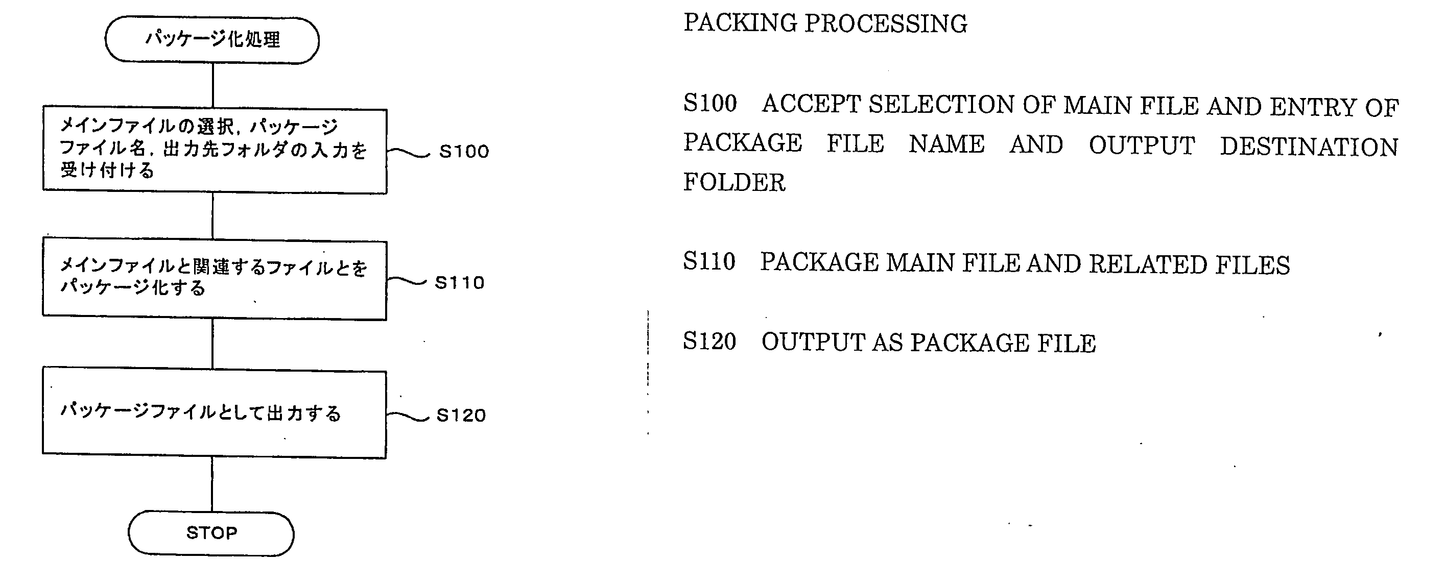
[0112] A file manipulation program as a first embodiment of the invention is a program concerning file manipulation in a computer and is made up of a packaging module for packaging a plurality of files and an unpackaging module for unpackaging a packaged file.

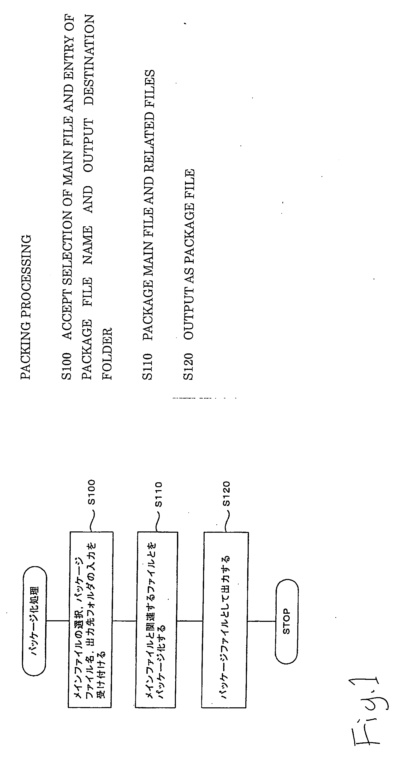
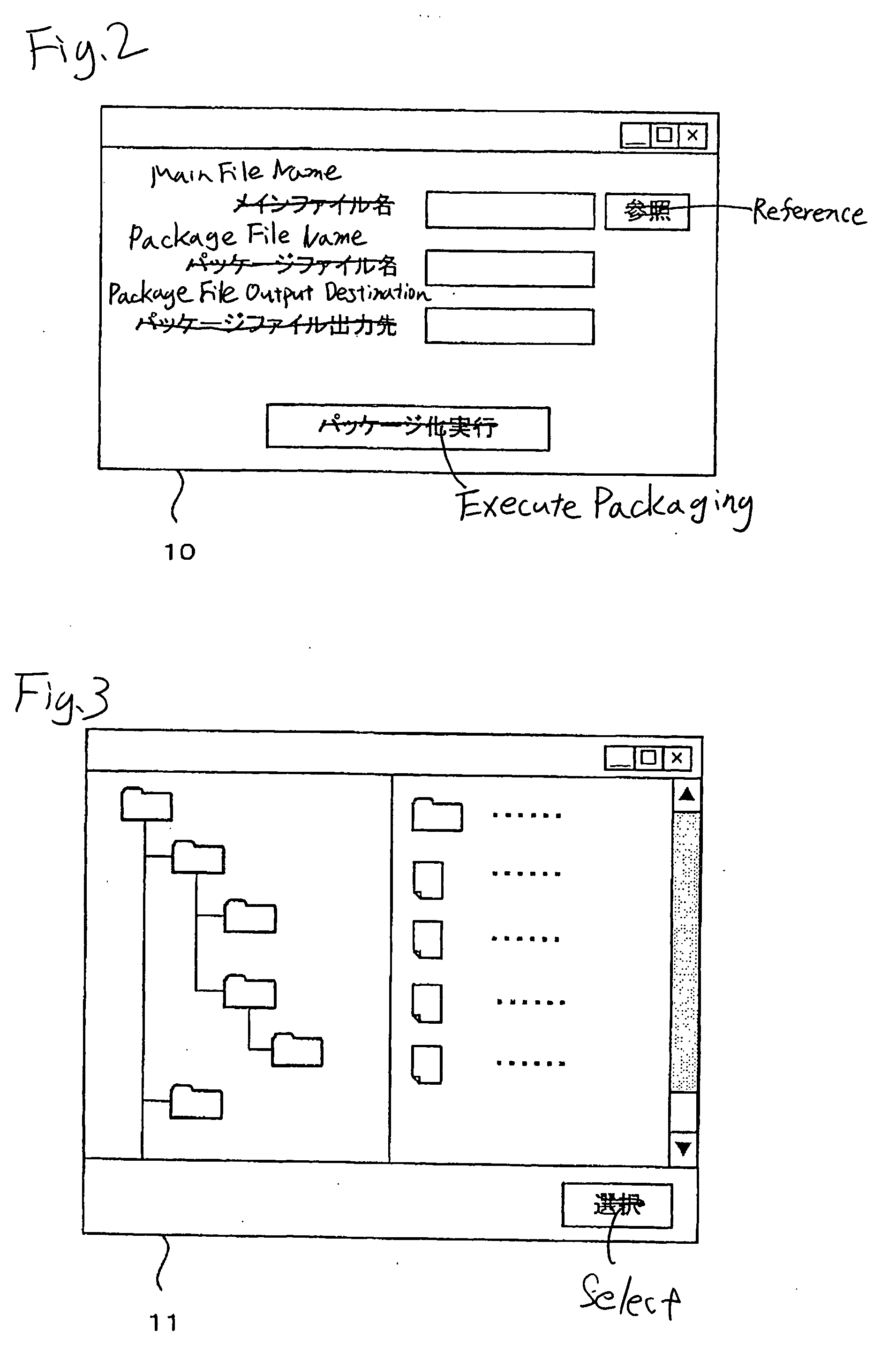
[0113]FIG. 1 is a flowchart to show an example of packaging processing in the file manipulation program of the first embodiment. In the packaging processing, first, selection of a main file and entry of the name of a package file, the output destination folder, etc., are accepted (step S100). The main file is a file to specify other related files to be packaged. The specification method is described later. In the first embodiment, selection of a main file, etc., is accepted through a packaging command screen. FIG. 2 shows an example of a packaging command screen 10. The packaging command screen 10 enables the user to enter the main file name, the package file name, and the package file output destination, as shown in the figur...

second embodiment

[0156]FIG. 21 is a schematic drawing to show an image processing system 201 according to a second embodiment of the invention. As shown in the figure, the image processing system 201 is made up of a digital still camera (DSC) 202 as an image output apparatus and a printer 203 as an image display apparatus. When a digital image file and a layout definition file stored in the DSC 202 are output, they are packaged into a single package file together with other files described later and the package file is written into removable memory 223. The printer 203 reads the package file from the removable memory 223 and acquires necessary files by unpackaging means and prints.

[0157]FIG. 22 is a block diagram to show the configuration of the DSC 202. FIGS. 23 (A) and 23 (B) are a front view and a rear view to show the appearance of the DSC 202.

[0158] An optical system 210 is made up of a lens 237, an aperture, etc., housed in a cabinet 230. The optical system 210 forms an optical image of a su...

third embodiment

[0200] In the description of a third embodiment, the case where a package file is transmitted to a communication line is taken as an example. Parts in the third embodiment substantially identical with those in the second embodiment will not be discussed again.

[0201]FIG. 37 is a schematic drawing to show an image processing system 204 according to the third embodiment of the invention. As shown in the figure, the image processing system 204 is made up of a DSC 206 as an image output apparatus and a personal computer (PC) 205 and a printer 207 connected to the PC 205 as an image display apparatus. The DSC 206 includes an output section configured in conformity with USB (Universal Serial Bus) standard as output means and likewise the PC 205 includes an input section configured in conformity with the USB standard as input means; the DSC 206 and the PC 205 are connected so that they can communicate with each other over a communication cable conforming to the USB standard. An image edit ...


PUM


Abstract

Selection of a main file and entry of the name of a package file, an output destination folder, etc., are accepted (step S100), the files in the folder of the same name as the main file existing in the same folder as the selected main file are packaged as related files (step S110), and the packaged files are output as a package file based on the entered name and the output destination folder (S120). Consequently, a plurality of electronic files can be packaged for easy handling.

Description

TECHNICAL FIELD [0001] This invention relates to an electronic file manipulation method and a layout edit apparatus and more particularly to a method used to manipulate an electronic file and a layout edit apparatus for editing the layout of an image area for displaying an image. [0002] The invention also relates to an image processing system and method. [0003] The invention also relates to a display data processing method, a display data structure, and a display data management method. BACKGROUND ART [0004] Hitherto, an apparatus for placing an image and a merge image area and editing the layout has been proposed as a layout edit apparatus. In the apparatus, to save the created layout, related electronic files such as an image file used for the layout are stored in a predetermined folder together with the electronic file of the layout. [0005] Compression software for combining a plurality of electronic files into one (for example, “LHA,”“WinZip,” etc.,) has been proposed as an elec...

Claims


Application Information

Patent Timeline
IPC IPC(8): G06F7/00G06F17/30G06F17/21G06F9/06G06F12/00H04N5/91
CPCG06F3/1215G06F3/125G06F3/1284G06T11/60H04N1/00204H04N1/00347H04N1/2158H04N1/32128H04N2101/00H04N2201/0084H04N2201/3229H04N2201/325
Inventor MOMOSE, HIROAKIKITAZAWA, TATSUYAKOMAGAMINE, KATSUMIOSHIKAWA, TATSURO
Owner SEIKO EPSON CORP
Learn More