
System and method for improved software simulation using a plurality of simulator checkpoints

a software simulation and checkpoint technology, applied in the field of system and method for simulating software, can solve the problems of large model size, difficult to simulate the model, and difficult to develop software for hardware that does not yet exist,

Inactive Publication Date: 2006-07-13
IBM CORP
View PDF5 Cites 42 Cited by
  • Summary
  • Abstract
  • Description
  • Claims
  • Application Information

AI Technical Summary

Benefits of technology

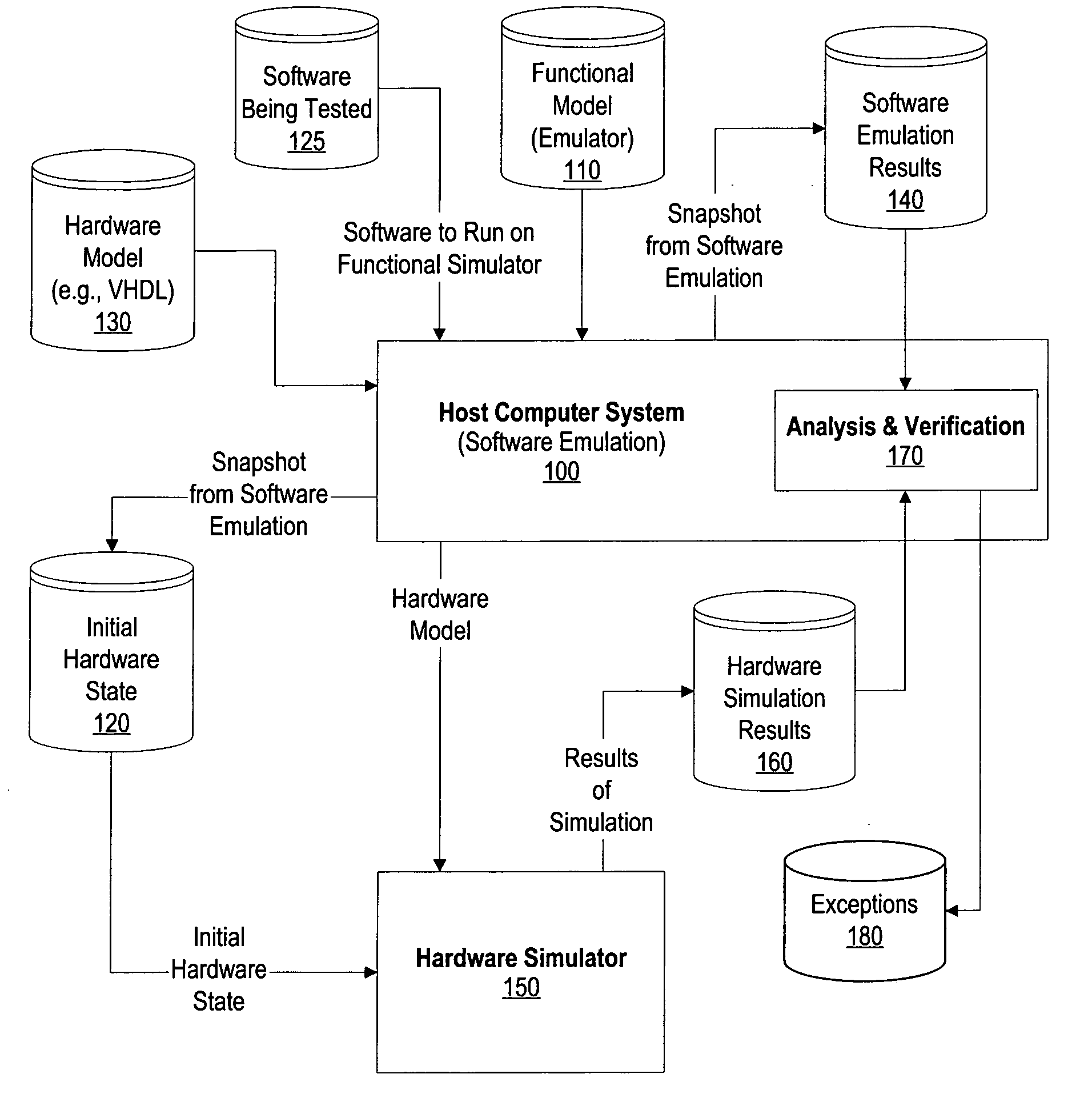
[0009] It has been discovered that the aforementioned challenges are resolved using a system and method that uses the speed of a software emulator coupled with the accuracy of a hardware simulator to test sections of software code. The software is emulated on a software emulator until the beginning of a section of code that is of interest. An initial “snapshot” is take

Problems solved by technology

Developing software for hardware that does not yet exist poses significant challenges.
Because of the complexity and enormous number of transistors in modern processors, the model can be quite large and simulating the model can be extremely slow.
While software, such as a base operating system, could be loaded as a test case and simulated, the time needed to complete the simulation, even on a very fast hardware-based simulator, is usually prohibitive.
While emulators typically are not able to run the software nearly as fast as the software is expected to run on the hardware, emulation allows the programmer to uncover problems and bugs in the software before the hardware is built.
One challenge of using an emulator, however, is that the emulator does not simulate the hardware that is being designed but rather imitates the functions that the hardware is supposed to provide.
In addition, the emulator is generally incapable of identifying timing problems with the hardware.

Method used


Image

  • System and method for improved software simulation using a plurality of simulator checkpoints
  • System and method for improved software simulation using a plurality of simulator checkpoints
  • System and method for improved software simulation using a plurality of simulator checkpoints

Examples


Embodiment Construction

[0020] The following is intended to provide a detailed description of an example of the invention and should not be taken to be limiting of the invention itself. Rather, any number of variations may fall within the scope of the invention which is defined in the claims following the description.

[0021]FIG. 1 is a diagram showing results from a functional simulation being used to seed a hardware model with an initial state and an analysis performed using the hardware simulation results and the functional simulation results. Host computer system 100 is used to perform functional simulation using functional model 110 of the system. Functional model 110 is a software emulator that emulates software as if it were running on the actual hardware. Host computer system 100 includes an operating system, such as Linux™ or IBM's AIX™, that has been slightly modified to perform a “snapshot” function when requested in the software that is being tested. Software emulator 110 is run by the operating...


PUM


Abstract

A system and method is provided to improve software simulation. A software emulator is used in conjunction with a hardware simulator. A special snapshot instruction is included in the software code that is emulated. When the snapshot instruction is encountered, values such as register, memory, and program stack values, are stored creating an initial snapshot. Code continues to be emulated and, when the next snapshot instruction is encountered, the values are written to create a second snapshot. The initial values are used to set an initial state in a hardware model that is simulated on a hardware simulator. The results of the hardware simulation are compared to the second snapshot to uncover software errors and / or hardware errors so that the software can be modified or the hardware design can be modified. Multiple sets of snapshots can be taken to analyze multiple sections of the software program.

Description

BACKGROUND OF THE INVENTION [0001] 1. Technical Field [0002] The present invention relates in general to a system and method for simulating software. More particularly, the present invention relates to a system and method for using software emulation in conjunction with hardware simulation to yield accurate yet expeditious results. [0003] 2. Description of the Related Art [0004] Software emulation and hardware simulation are two approaches that developers used to test hardware that is being designed as well as software that is being developed to run on the new hardware. Developing software for hardware that does not yet exist poses significant challenges. [0005] One approach to this challenge is using a hardware simulator to simulate the actual performance of the hardware design. The hardware is designed and coded into a design description language. One such language is “VHDL” which stands for VHSIC Hardware Description Language (with VHSIC standing for Very High Speed Integrated Ci...

Claims


Application Information

Patent Timeline
IPC IPC(8): G06F9/455
CPCG06F17/5022G06F30/33
Inventor AGUILAR, MAXIMINO JR.BOHRER, PATRICK JOSEPHSTAFFORD, JAMES MICHAEL
Owner IBM CORP
Learn More