
On-demand group communication services with quality of service (QoS) guarantees

a group communication and quality assurance technology, applied in the field of on-demand group communication, can solve the problems of not taking into account the “last-mile” problem, the supply of internet backbone bandwidth has kept pace, and the “last-mile” bandwidth available to residences and small businesses remains a severe limitation

Active Publication Date: 2006-07-13
HULU
View PDF3 Cites 38 Cited by
  • Summary
  • Abstract
  • Description
  • Claims
  • Application Information

AI Technical Summary

Benefits of technology

[0010] The present invention broadly contemplates addressing QoS concerns in overlay design to account for the last mile problem. In accordance with the present invention, a simple queuing network model for bandwidth usage in the last-mile bottlenecks is used to capture the effects of the asymmetry, the contention for band

Problems solved by technology

These efforts, however, do not take into account the “last-mile” problem in terms of the contentions and the asymmetry.
Indeed, the supply of Internet backbone bandwidth has kept pace with (and often surpassed) increasing demand, while the “last mile” bandwidth available to residences and small businesses remains a severe limitation.
With the advent of WDM (Wavelength Division Multiplexing) technologies, this problem will only become more stringent.
When end-system multicast is deployed, this upstream capacity bottleneck scenario results in significant contention on the bottleneck link, with multiple connections vying for their share of the bandwidth.
This requires several times more upstream bandwidth than downstream, further exaggerating the already asymmetric nature of many last-mile links.
As a result, packets may arrive at an end system much faster than it is capable of forwarding the replicated copies, causing them to queue up in the operating system and / or network interface buffers.
These efforts, however, do not explicitly account for the queuing delays caused by contention for last mile bandwidth bottlenecks and sharing of this last mile with link asymmetry.
These issues influence the outcome of the constructed overlay as the available bandwidth for each forwarding link is dependent on the node forwarding fanout.

Method used


Image

  • On-demand group communication services with quality of service (QoS) guarantees
  • On-demand group communication services with quality of service (QoS) guarantees
  • On-demand group communication services with quality of service (QoS) guarantees

Examples


Embodiment Construction

[0019] The overlay construction process is preferably addressed in two phases in accordance with the present invention. The first is the selection of a “forwarding degree’” (the number of receivers to which an end-system should forward incoming data) for each end-system that will forward data (many nodes will only receive data, and thus have a forwarding degree of zero). This selection has direct implications for the queuing and propagation delays and the packet loss. On one extreme, a chain topology (where each node forwards to one other) minimizes link stress (and therefore queuing latency / loss) but maximizes network transit latency. On the other extreme, a star configuration (where a single node forwards to all others) would minimize network latency at the expense of increasing link stress (and queuing loss). The second phase of overlay construction is the selection of the position (i.e. the parent) of each node in the overlay tree. This problem is NP (nondeterministic polynomial...


PUM


Abstract

The present invention broadly contemplates addressing QoS concerns in overlay design to account for the last mile problem. In accordance with the present invention, a simple queuing network model for bandwidth usage in the last-mile bottlenecks is used to capture the effects of the asymmetry, the contention for bandwidth on the outgoing link, and to provide characterization of network throughput and latency. Using this characterization computationally inexpensive heuristics are preferably used for organizing end-systems into a multicast overlay which meets specified latency and packet loss bounds, given a specific packet arrival process.

Description

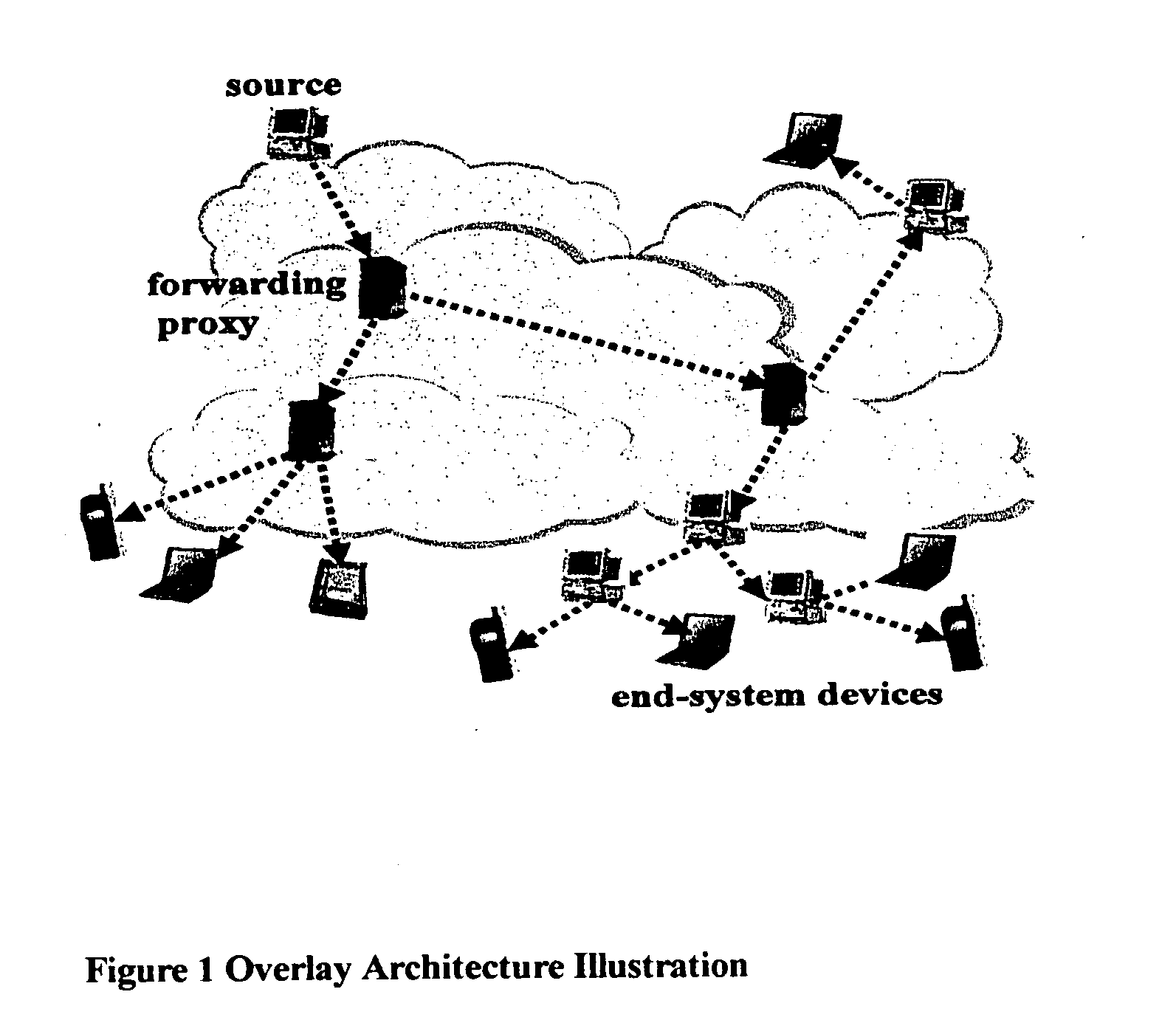
FIELD OF THE INVENTION [0001] The present invention generally relates to on-demand group communications supporting quality of service sensitive applications. More specifically, the invention relates to the construction of overlay networks in on-demand group communication. BACKGROUND OF THE INVENTION [0002] Throughout the instant disclosure, numerals in brackets—[ ]—are keyed to the list of numbered references towards the end of the disclosure. [0003] A growing number of applications are using overlay network support to provide a variety of value added services in the Internet, e.g., CDN (Content Delivery Network) based services, collaborative applications such as video conferencing, instant messaging, secure network services. Typically in an overlay based communication, a forwarding tree is constructed using participating end-system devices and (optionally) forwarding servers to distribute content. This has been advocated as a practical alternative architecture to IP-multicast for s...

Claims


Application Information

Patent Timeline
IPC IPC(8): H04L12/28
CPCH04L12/185H04L12/1854H04L12/66H04L41/0896H04L41/145H04L41/5009H04L41/5051H04L41/509
Inventor DUBE, PARIJATLIU, ZHENSAHU, SAMBIT
Owner HULU
Learn More