
Power system method and apparatus

a power system and power system technology, applied in the direction of basic electric elements, electric generators, transportation and packaging, etc., can solve the problems of increasing cost, limiting the operating range, and high cost of higher-rated semiconductor devices

Inactive Publication Date: 2006-07-13
SIEMENS VDO AUTOMOTIVE CORP
View PDF99 Cites 362 Cited by
  • Summary
  • Abstract
  • Description
  • Claims
  • Application Information

AI Technical Summary

Benefits of technology

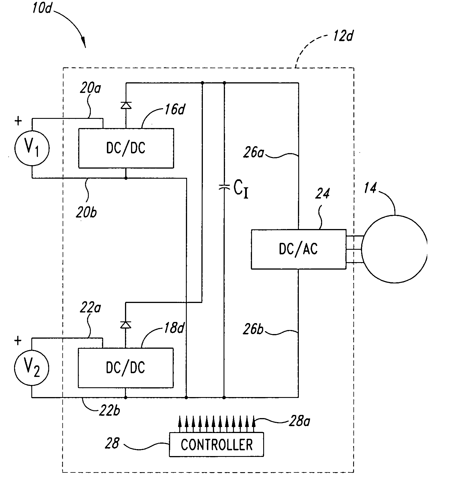
[0066]FIG. 46 is a schematic diagram of a bi-directional system wherein an additiona

Problems solved by technology

This may require the use of higher rated semiconductor devices, which are expensive.
This may also create thermal management problems which may limit the operating range, increase cost, increase size and / or weight, adversely effect efficiency and / or reduce reliability of a power converter.

Method used


Image

  • Power system method and apparatus
  • Power system method and apparatus
  • Power system method and apparatus

Examples


Embodiment Construction

[0068] In the following description, certain specific details are set forth in order to provide a thorough understanding of various embodiments of the present systems and methods. However, one skilled in the relevant art will recognize that the present systems and methods may be practiced without one or more of these specific details, or with other methods, components, materials, etc. In other instances, well-known structures associated with converter systems and power sources, and associated methods and apparatus have not been shown or described in detail to avoid unnecessarily obscuring descriptions of the embodiments of the present systems and methods.

[0069] Unless the context requires otherwise, throughout the specification and claims which follow, the word “comprise” and variations thereof, such as, “comprises” and “comprising” are to be construed in an open, inclusive sense, that is as “including, but not limited to.”

[0070] Reference throughout this specification to “one embo...


PUM


Abstract

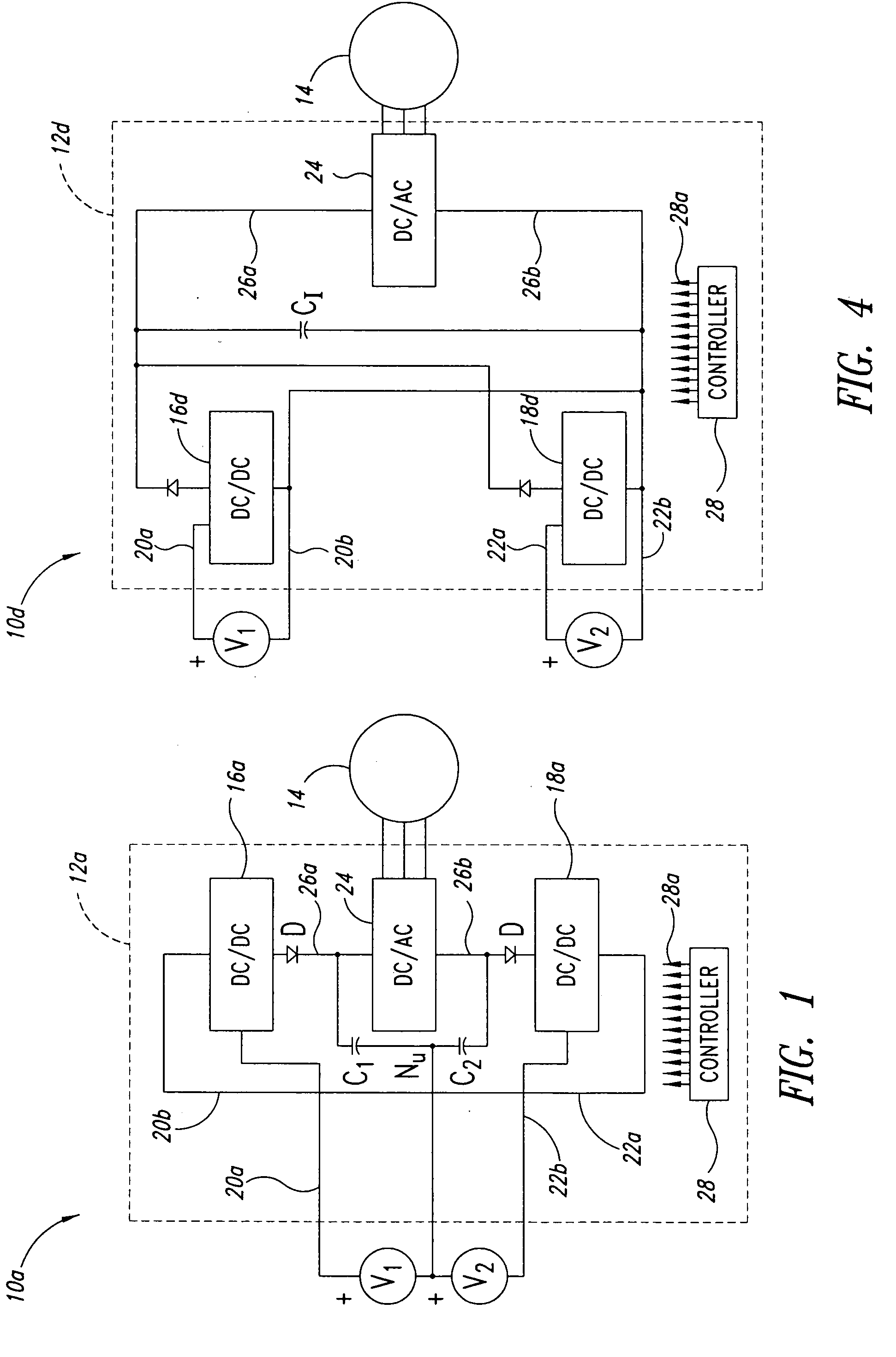
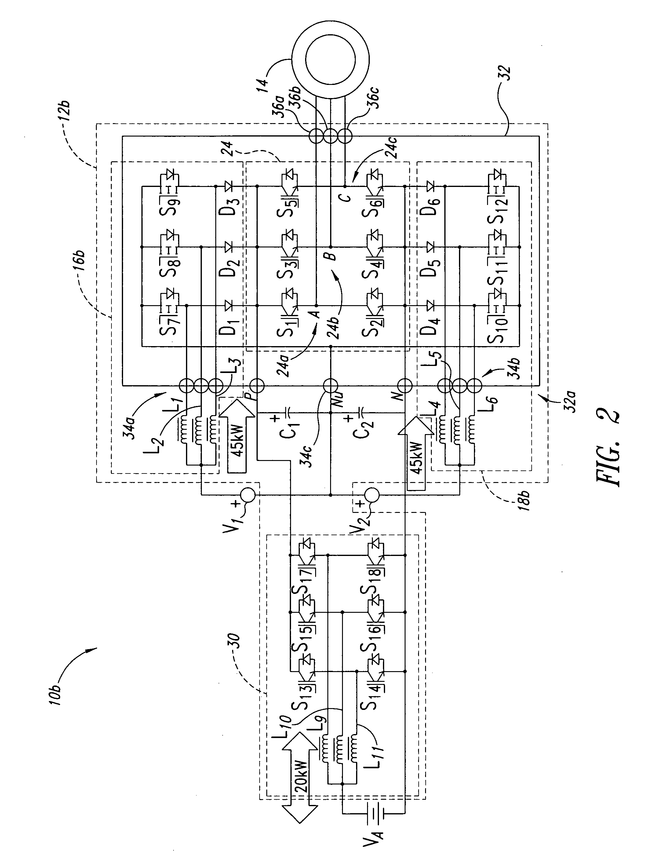
Power converter system topologies comprise a first DC / DC converter to pull a positive rail of a high voltage bus up, while a second DC / DC converter pushes a negative rail of the high voltage bus down. One or both the DC / DC converters may be bi-directional. Such topologies are suitable for use with separate primary power sources, and / or auxiliary power sources. Such topologies may include a DC / AC converter, which may be bi-directional. Such topologies may include one or more auxiliary DC / DC converters, which may be bi-directional. Multiple substrates, including at least one stacked above another may enhance packaging.

Description

CROSS-REFERENCES TO RELATED APPLICATIONS [0001] This application claims the benefit under 35 U.S.C. § 119(e) of U.S. Provisional Patent Application No. 60 / 621,012 filed Oct. 20, 2004; U.S. Provisional Patent Application No. 60 / 662,707 filed Mar. 17, 2005; and U.S. Provisional Patent Application No. 60 / 688,310 filed Jun. 7, 2005, where these three provisional applications are incorporated herein by reference in their entireties.BACKGROUND OF THE INVENTION [0002] 1. Field of the Invention [0003] This disclosure generally relates to electrical power systems, and more particularly to power system architectures suitable for rectifying, inverting, and / or converting electrical power between power sources and loads. [0004] 2. Description of the Related Art [0005] Power conversion systems transform and / or condition power from one or more power sources for supplying power to one or more loads. A power conversion system component commonly referred to as an “inverter” transforms direct current ...

Claims


Application Information

Patent Timeline
IPC IPC(8): H02J3/00
CPCB60L9/30B60L2200/26B60L2210/20B60L2210/40H01M8/04537H01M8/04858H01M8/249H02M7/003H02M7/487H02M2001/0074Y02E60/50Y02T10/7216Y02T10/7241Y02T10/725B60L2210/10H01L2224/49175H01L2924/13055H01L2924/13091Y02T10/72H02M1/0074H02M1/0085H01L2224/49111H01L2224/49113H01L2924/19107H01L2924/00
Inventor FLETT, FREDZHU, LIZHIAHMED, SAYEEDPATWARDHAN, AJAY V.DAVIS, ROY I.
Owner SIEMENS VDO AUTOMOTIVE CORP
Learn More