Eureka AIR delivers breakthrough ideas for toughest innovation challenges, trusted by R&D personnel around the world.

Steerable catheter and methods of making the same

a catheter and sheath technology, applied in the field of flexible tubular bodies, can solve the problems of increasing the difficulty of operating the deflection wire, causing friction between the deflection wire and the actuation force, and braid embedded in the outer wall of the body

Active Publication Date: 2006-07-13
ST JUDE MEDICAL ATRIAL FIBRILLATION DIV
View PDF14 Cites 40 Cited by
  • Summary
  • Abstract
  • Description
  • Claims
  • Application Information

AI Technical Summary

Benefits of technology

[0011] The present invention, in one embodiment, is a flexible tubular body of a catheter, sheath or similar medical device. The body comprises a deflection wire residing within a wire lumen having an inner diameter that exceeds the outer diameter of the deflection wire. During the manufacturing of the body, the wire lumen is injected with a fluid to prevent a reduction in the inner diameter.
[0014] In one embodiment, the body also includes a fluid residue within wire lumen. The residue helps to lubricate the displacement of the deflection wire through the wire lumen.

Problems solved by technology

This creates three related difficulties.
First, significant deflection wire actuation friction is created between the walls of the wire lumens and the deflection wires as an operator attempts to deflect the body by moving the deflection wires.
This actuation friction increases the difficulty in operating the deflection wires.
Second, as the distal end of the body is deflected (bent) through the movement of the deflection wires, the wire braid embedded in the outer wall of the body is also flexed.
This can cause the wire braid to lock down on the deflection wires and the wire lumens.
The third problem is that as the deflection wires are “locked down” in the bent body, the deflection wires and body loses the ability to spring back to the original shape as the force on the deflection wires from the operator at the proximal end is removed.
However, it does so at the cost of increased manufacturing complication, waste and, as a result, expense.

Method used


Image

  • Steerable catheter and methods of making the same
  • Steerable catheter and methods of making the same
  • Steerable catheter and methods of making the same

Examples


Embodiment Construction

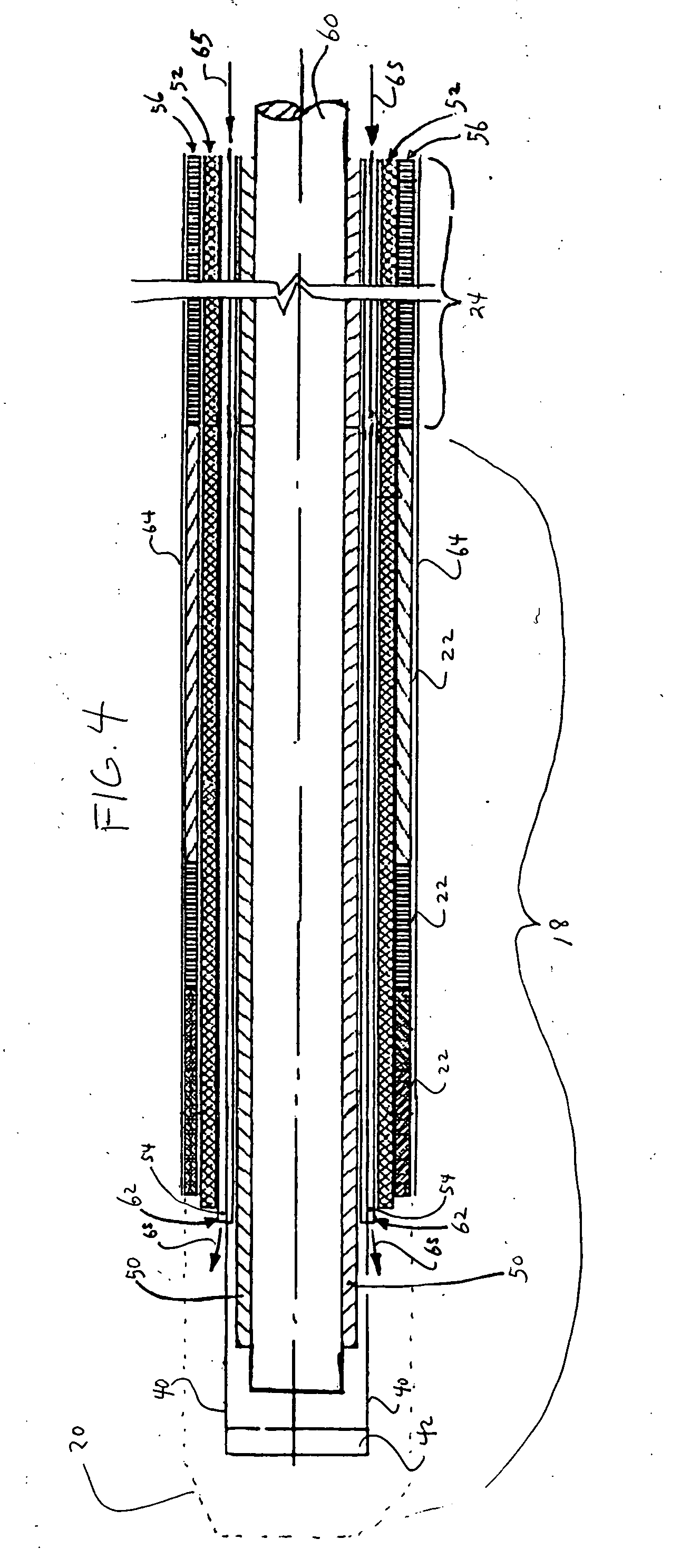
[0021] The present invention, in one embodiment, is a flexible tubular body for a steerable catheter, sheath or similar medical device that offers reduced deflection wire actuation friction and locking problems, but is less expensive and complicated to manufacture, as compared to prior art methods. During manufacturing of the flexible tubular body, oversized wire lumens are formed about deflection wires embedded in the wall of the body by injecting a pressurized fluid between the circumferential surfaces of the wire lumen and the deflection wire located therein.

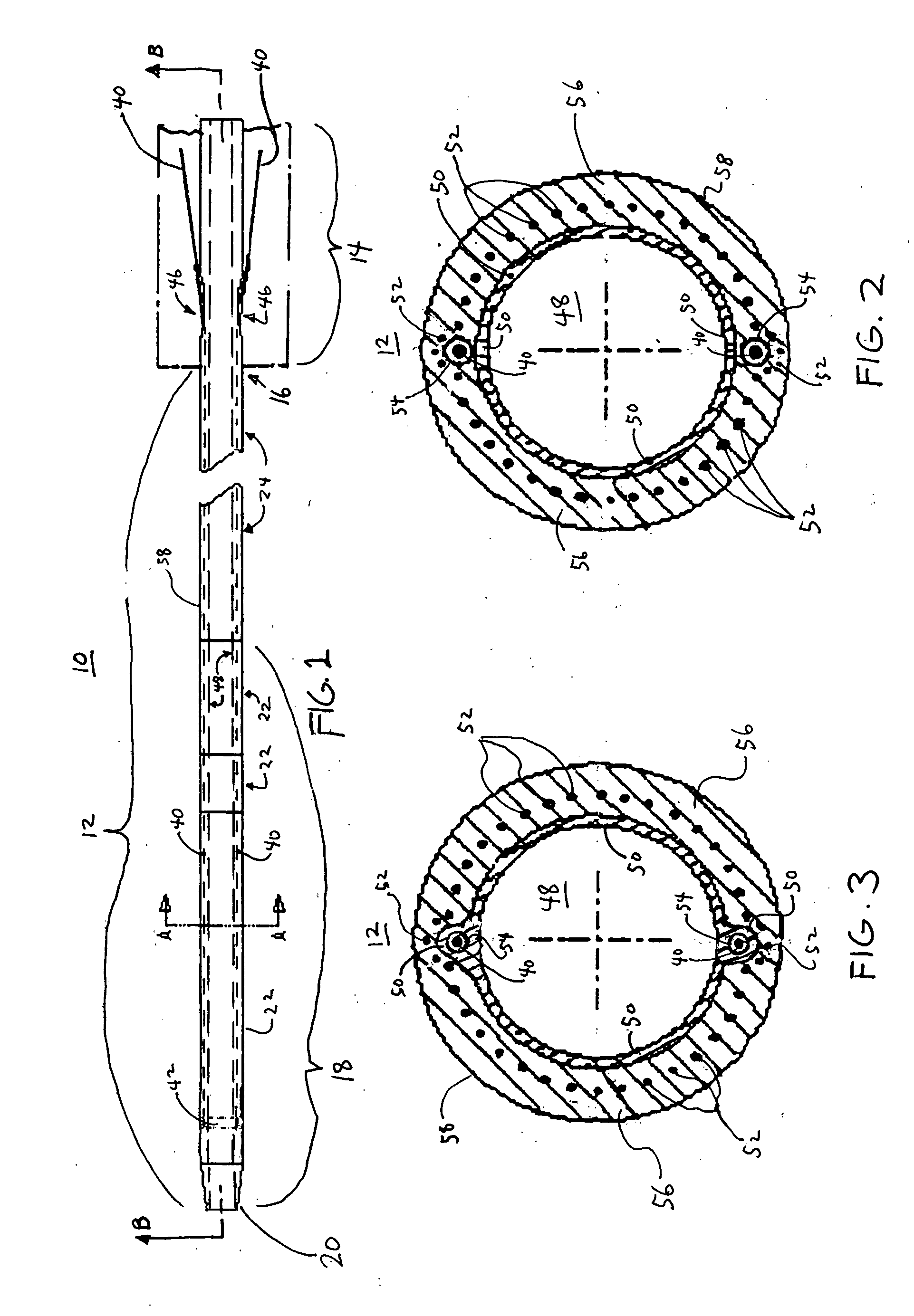
[0022] For a discussion of a steerable catheter or sheath 10 employing the flexible tubular body 12 of the present invention, reference is now made to FIG. 1, which is a side view of the catheter or sheath 10. As shown in FIG. 1, the catheter or sheath 10 includes a generally tubular flexible body 12 and an actuation handle 14 coupled to a proximal end 16 of the body 12. A distal end 18 of the body 12 is adapted to deflect (...


PUM

PropertyMeasurementUnit
temperatureaaaaaaaaaa
outer diameteraaaaaaaaaa

Abstract

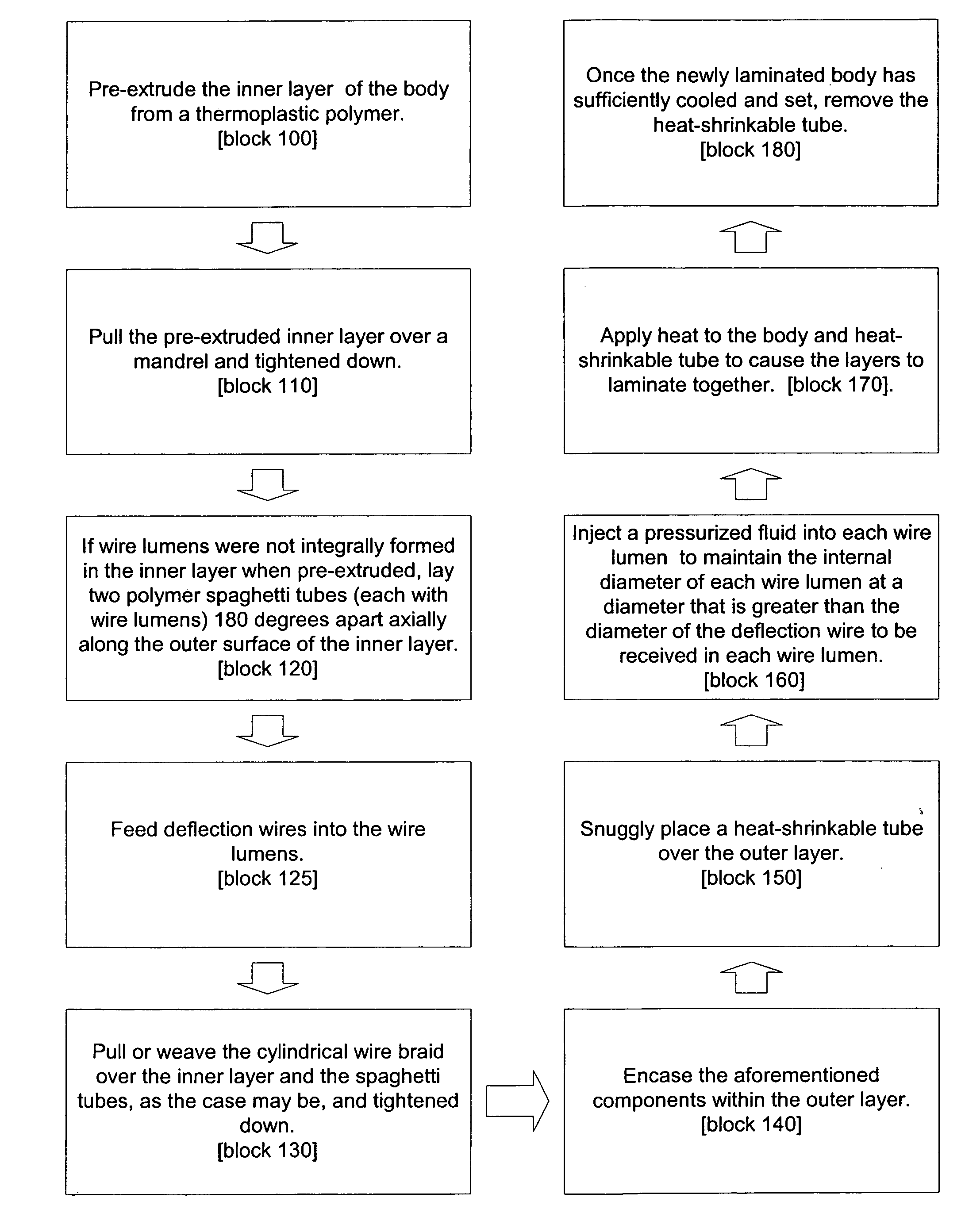
The present invention is a method of manufacturing a flexible tubular body for catheter, sheath or similar medical device. The method comprises pre-extruding an inner layer of the body from a thermoplastic polymer and then pulling the inner layer over a mandrel and tightening the layer down. If wire lumens were not integrally formed in the inner layer when pre-extruded, then two polymer spaghetti tubes, each with wire lumens, are laid 180 degrees apart axially along the outer surface of the inner layer. Deflection wires are then fed into the wire lumens. A cylindrical wire braid is woven or pulled over the inner layer (and the spaghetti tubes, as the case may be) and tightened down. The aforementioned components are then encased in an outer polymer layer. A heat-shrinkable tube is then placed over the outer layer. A pressurized fluid is injected into each wire lumen to maintain the internal diameter of each wire lumen at a diameter that is greater than the diameter of the deflection wire received in each wire lumen. Heat is then applied to the body and heat-shrinkable tube to cause the layers to laminate together. Once the newly laminated body has sufficiently cooled, the heat-shrinkable tube is removed from the body.

Description

FIELD OF THE INVENTION [0001] The present invention relates to catheters and sheaths and methods of making and using catheters and sheaths. More particularly, the present invention relates to the flexible tubular bodies of steerable catheters or sheaths and methods of making and using such bodies. BACKGROUND OF THE INVENTION [0002] A current method in the art used to manufacture flexible tubular bodies of steerable catheters or sheaths is to form the body on a mandrel using multiple layers: an inner liner intended to define the central lumen of the body; a layer of wire braid for reinforcing the body; and an outer thermoplastic jacket. The inner liner is pulled over the mandrel and tightened down. Deflection wires used to deflect the distal tip of the body are laid axially along the inner liner. The layer of wire braid is pulled or woven over the inner liner and deflection wires. After the wire braid is tightened down, the entire body is encased in a thermoplastic outer jacket. The ...

Claims


Application Information

Patent Timeline
Patent Type & Authority Applications(United States)
IPC IPC(8): B29C43/10A41D19/00
CPCA61M25/0012A61M25/0045A61M25/005A61M25/0147B29D23/00
Inventor WILKOWSKE, ERIC JOHNFUENTES, ALLAN MANUELGUO, XIAOPINGKHIEU, XUAN YENNEMEC, LINDA KAYSTEHR, RICHARD E.
Owner ST JUDE MEDICAL ATRIAL FIBRILLATION DIV
Why Eureka
Eureka Blog
Learn More