Male header connector device

Active Publication Date: 2006-07-06
J S T CORP
View PDF23 Cites 8 Cited by
  • Summary
  • Abstract
  • Description
  • Claims
  • Application Information

AI Technical Summary

Benefits of technology

[0012] In addition, the invention provides a connector device wherein the asymmetrical surface allows for the reduction of the packaging size of the terminals and a reduction of the size of the terminals.
[0014] Furthermore, the invention provides a connector device in which the terminals may be positioned relative to the asymmetrical surface such that the terminals are scoop-proof. As will be known to a person of ordinary skill in the art, a scoop-proof design is a design that minimizes the possibility for contact damage to the terminals.
[0015] The designs of the invention yield many advantages. For example, the length of the terminals inside the receptacle portion can be optimized to the ideal length by moving the asymmetrical surface in and out. In addition, the length of the terminals extending behind the connector housing can be optimized for all rows by moving the rows closer to the PCB in and out. Furthermore, the overall total packaging size of the male header can be optimized. Also, the terminals in the center of the connector device can be recessed back to aid in scoop-proofing the connector system.

Problems solved by technology

These types of headers encounter various problems.
For example, for connections that have multiple rows or columns of terminals, this puts limitations on the pin or blade length protruding from the retaining surface as some pins or blades may be required to be longer than needed because of varying terminal sizes inside the single connector.

Method used


Image

  • Male header connector device
  • Male header connector device
  • Male header connector device

Examples


Embodiment Construction

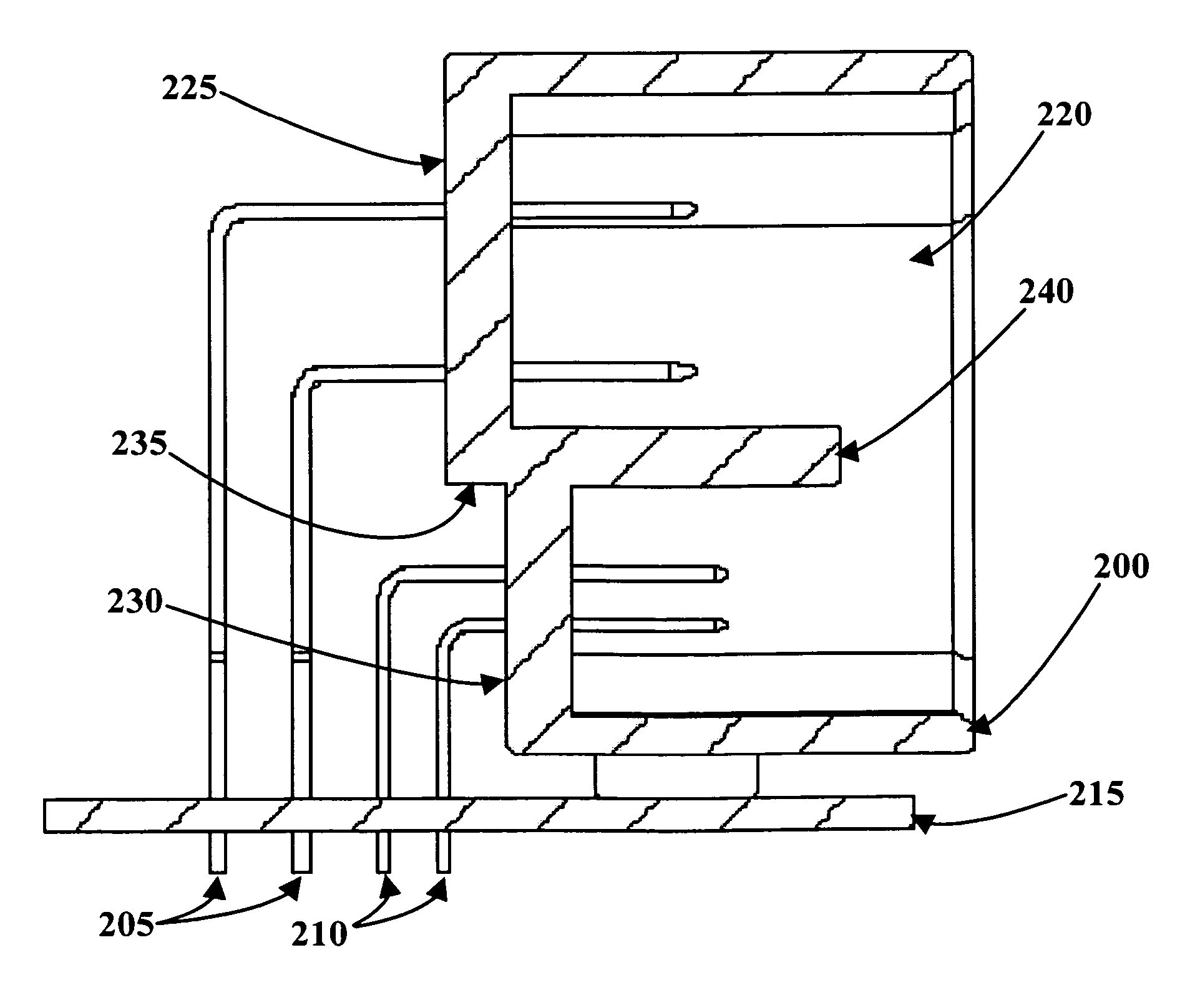
[0034] As is shown in FIG. 6, an embodiment of the invention relates to a male header connector device in which a plurality of rows of terminals 205 and 210 of varying heights extend upwards from a surface of a circuit board 215 and into a connector housing 200. Connector housing 200 defines a receptacle portion 220, and includes an asymmetrical surface comprising, for example, retention surfaces 225 and 230. Terminals 205 and 210 extend through the asymmetrical surface via retention surfaces 205 and 210, respectively, and extend into receptacle portion 220. The asymmetrical surface comprises a plurality of substantially parallel vertical sections (i.e. retention surfaces 225 and 230) separated by at least one substantially horizontal section 235. In this embodiment, horizontal section 235 extends into receptacle portion 220 as a divider 240, which separates the terminal rows 205 from terminal rows 210 inside receptacle portion 220. The horizontal and vertical sections of the asymme...


PUM


Abstract

The invention relates to a connector device that includes a plurality of terminals of varying heights that extend upwardly from the surface of a circuit board, and a connector housing that defines a receptacle portion. The connector housing includes an asymmetrical surface adapted to receive a plurality of terminals, and each of the plurality of terminals extends through a portion of the asymmetrical surface into the receptacle portion of the connector housing. The asymmetrical surface may include a plurality of substantially parallel vertical sections separated by at least one substantially horizontal section, may be angled relative to the surface of the circuit board, or may be curved relative to the surface of the circuit board. In addition, at least a portion of the asymmetrical surface of the connector housing may protrude over at least a portion of at least one of the terminals extending between the circuit board and the asymmetrical surface. In addition, the invention provides a connector device wherein the asymmetrical surface allows for the reduction of the packaging size of the terminals and a reduction of the size of the terminals.

Description

RELATED APPLICATION DATA [0001] This application claims benefit of priority of Provisional Application Ser. No. 60 / 634,239 filed on Dec. 9, 2004, the entire disclosure of which is incorporated herein by reference.FIELD OF THE INVENTION [0002] The invention relates generally to male header connector devices. More specifically, the invention relates to a male header connector device that utilizes a connector housing having an asymmetrical surface that is adapted to receive a plurality of terminals that extend from a circuit board. BACKGROUND [0003] Existing single-level male headers in an electrical connection are typically comprised of a housing that has a single surface for the male pin or blade terminals to be retained. FIGS. 1-5 illustrate various known configurations for male header connectors. In particular, these figures show a variety of connectors wherein a plurality of terminals 105 extend upwardly from a circuit board 110 through a surface 115 and into a receptacle portion ...

Claims


Application Information

Patent Timeline
IPC IPC(8): H01R13/40
CPCH01R12/716H01R27/02
Inventor DILLON, CHRISTOPHER J.CHEN, PING
Owner J S T CORP
Why Eureka
Try Eureka