
Microminiature gas chromatograph column

Inactive Publication Date: 2006-07-06
CAPITALBIO CORP +1
View PDF8 Cites 31 Cited by
  • Summary
  • Abstract
  • Description
  • Claims
  • Application Information

AI Technical Summary

Benefits of technology

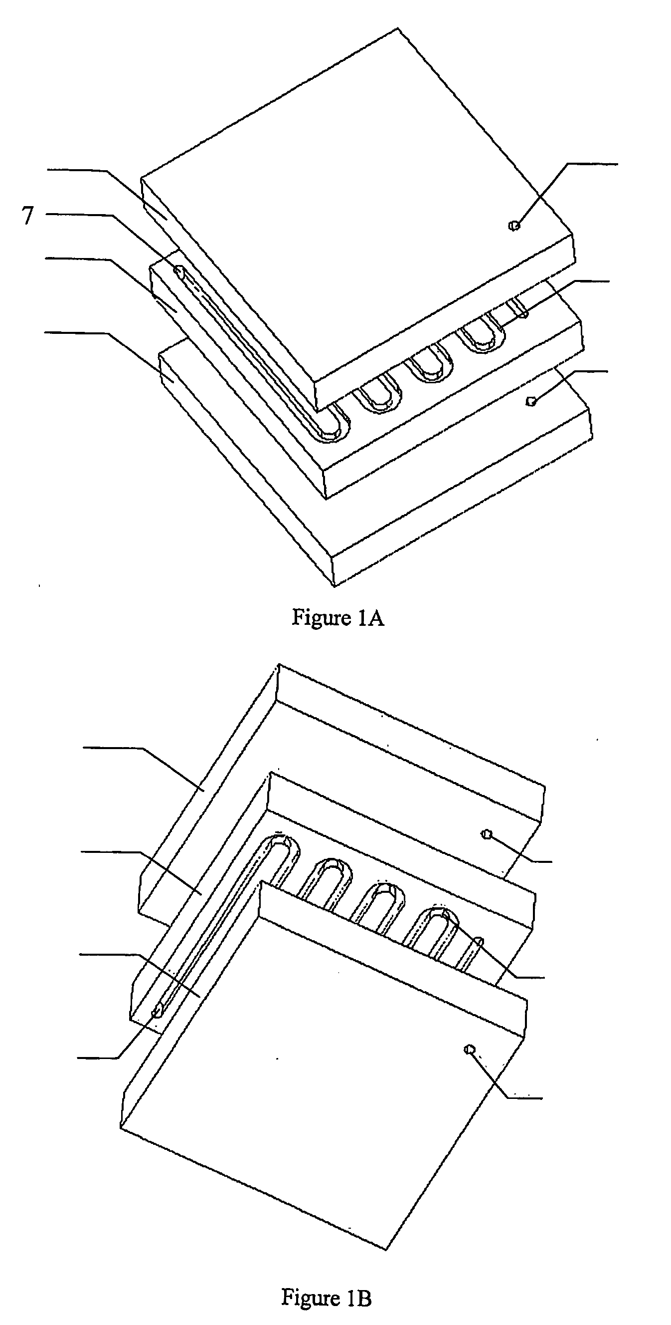
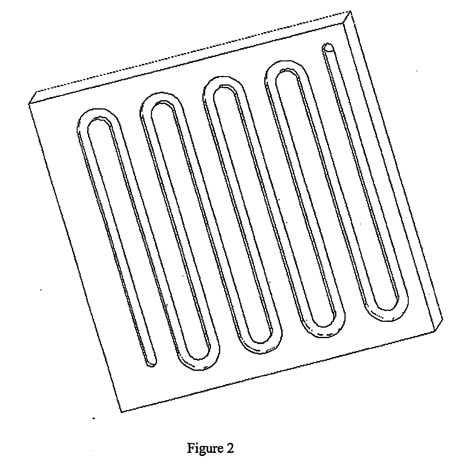
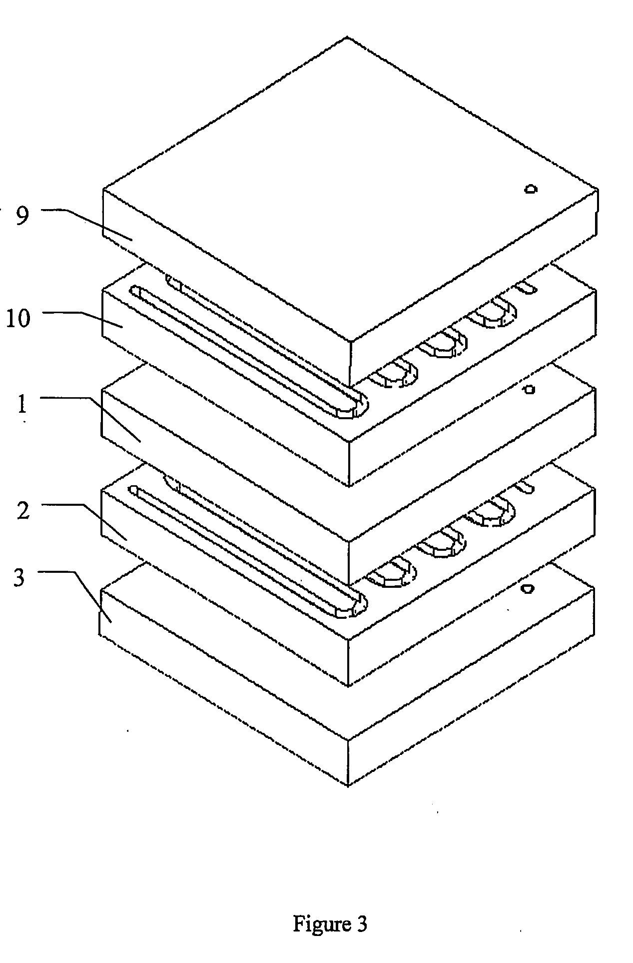
[0045] An advantage of this specific embodiment is that it arranges the capillaries in the column into no less than 2 layers and provides a more compact structure than that of the prior microfabricated gas chromatograph columns. Another advantage of this specific embodiment is that the extension of the number of layers is made relatively easy.
[0008] In still another aspect, the present invention is directed to a gas chromatograph system, which system comprises: a) a gas injector for introducing a mobile phase including a sample gas in a carrier gas; b) an above-described gas chromatograph column comprising a stationary phase suitable for gas chromatograph and mechanically connected to receive said mobile phase from said gas injector for the separation of an analyte in said sample gas; and c) a detector mechanically connected to said column for the analysis of said separated analyte of said sample gas with an electronic means.
[0009] In yet another aspect, the present invention is directed to a method for analyzing an analyte in a sample, which method comprises: a) providing an above-described gas chromatograph system; b) vaporizing a sample to a gas phase; c) injecting said sample gas in a carrier gas into said gas chromatograph system; and d) allowing separation and detection of an analyte in said sample in said gas chromatograph system to assess the presence, absence or amount of said analyte in said sample.

Problems solved by technology

Prior art equipment can provide useful results, but such equipment is extraordinary bulky and too delicate to be called portable.
The prior art, however, has not succeeded in the analysis of certain liquid samples with microfabricated gas chromatograph columns.
The main reason is that the microfabricated gas chromatograph columns are not long enough to attain satisfying separation effects.

Method used


Image

  • Microminiature gas chromatograph column
  • Microminiature gas chromatograph column
  • Microminiature gas chromatograph column

Examples


Embodiment Construction

[0013] For clarity of disclosure, and not by way of limitation, the detailed description of the invention is divided into the subsections that follow.

A. DEFINITIONS

[0014] Unless defined otherwise, all technical and scientific terms used herein have the same meaning as is commonly understood by one of ordinary skill in the art to which this invention belongs. All patents, applications, published applications and other publications referred to herein are incorporated by reference in their entirety. If a definition set forth in this section is contrary to or otherwise inconsistent with a definition set forth in the patents, applications, published applications and other publications that are herein incorporated by reference, the definition set forth in this section prevails over the definition that is incorporated herein by reference.

[0015] As used herein, “a” or “an” means “at least one” or “one or more.”

[0016] As used herein, “chromatography” refers to a method to separate, identi...


PUM


Abstract

This invention relates to the field of miniaturing gas chromatograph instruments using microfabrication technologies. In particular, the invention provides a gas chromatograph column, which column comprises at least two lid layers and a channel layer, wherein each of said layers comprises a compact material suitable for gas chromatograph, said channel layer comprises microfabricated channels on both sides, said microfabricated channels and a side of said lid layers form at least two capillaries, said at least two capillaries are connected to each other through a hole in said channel layer to form an integrated capillary, said integrated capillary is connected to outside atmosphere on both ends via holes on two outmost lid layers to serve as an inlet and an outlet.

Description

TECHNICAL FIELD [0001] This invention relates to the field of miniaturing gas chromatograph instruments using microfabrication technologies. In particular, the invention provides for a gas chromatograph column, which column comprises at least two lid layers and a channel layer, wherein each of said layers comprises a compact material suitable for gas chromatograph, said channel layer comprises microfabricated channels on both sides, said microfabricated channels and a side of said lid layers form at least two capillaries, said at least two capillaries are connected to each other through a hole in said channel layer to form an integrated capillary, said integrated capillary is connected to outside atmosphere on both ends via holes on two outmost lid layers to serve as an inlet and an outlet. BACKGROUND ART [0002] Gas chromatographs are used by various scientific laboratories and government law enforcement agencies to analyze the chemical makeup of samples of materials. Some of such i...

Claims


Application Information

Patent Timeline
IPC IPC(8): B01D53/02B01D53/14G01N30/02G01N30/60
CPCG01N30/6039G01N30/6095G01N2030/025
Inventor LIANG, DONGXING, WANLICHENG, JING
Owner CAPITALBIO CORP
Learn More