
Patient warming system

a patient and heating system technology, applied in the field of patient care, can solve problems such as patient chilling, patient hypothermia, and animal cooling

Inactive Publication Date: 2006-06-29
DUNLOP COLIN
View PDF29 Cites 5 Cited by
  • Summary
  • Abstract
  • Description
  • Claims
  • Application Information

AI Technical Summary

Benefits of technology

[0012] The pervious material is adjacent to, in use, a patient receiving treatment. Delivering heat spread over the surface of the porous material advantageously has the effect of evenly warming the patient without forming relatively high velocity streams of air (as in the prior art blanket where the air is delivered via discreet holes). Animals, therefore, and in particular small animals, are not at risk of being cooled by relatively high velocity air streams. In one embodiment, a substantial proportion of the surface of the one layer is of porous material. Preferably, a majority of the surface of the one layer is of porous material. In operation, warm area is advantageously delivered at relatively low velocity over the proportion of the surface of the one layer.
[0013] Preferably, the blanket is designed not to cover the animal patient, but instead to provide a patient receiving area in which the patient lies surrounded at least on three sides by a tube formed by the blanket when air is pumped into the air space. In this embodiment, at least the sides of the tube facing inwards towards the patient are of the porous material. This has the effect of passing warm air over the patient within the space, so no matter how large the patient, the air in the space will be kept at substantially the same temperature.
[0015] In an alternative embodiment, the entire blanket may be made of porous material so that warmed air is delivered over the entire surface of the blanket that is exposed. The unexposed surface of the blanket e.g. facing down on a bench, may not deliver air. The exposed surface, however, including the surface which may be adjacent to patient in operation, will deliver air. This saves cost in manufacture of the blanket as it is only necessary to manufacture the blanket from one type of material. This can be significant, as in the majority of cases these blankets are intended to be disposable after one use.
[0016] In an alternative embodiment, the entire blanket may be made of porous material so that warmed air is delivered over the entire surface of the blanket that is exposed. The unexposed surface of the blanket e.g. facing down on a bench, may not deliver air. The exposed surface, however, including the surface which may be adjacent to patient in operation, will deliver air. This saves cost in manufacture of the blanket as it is only necessary to manufacture the blanket from one type of material. This can be significant, as in the majority of cases these blankets are intended to be disposable after one use.
[0022] In accordance with a fifth aspect, the present invention provides a method of warming a patient during surgery, comprising the steps of receiving the patient within a patient receiving space within which the patients body is accessible for surgery, and passing warmed air into the patient receiving space to keep the patient warm.

Problems solved by technology

There are a number of problems associated with the use of the human patient warming system in veterinary care, however.
Small animals have a relatively large surface area to volume ratio, which makes them particularly susceptible to hypothermia.
The applicants have found that using a conventional human warming system to maintain the body temperature of a relatively small animal can actually result in cooling of the animal (which can lead to death).
In a patient with relatively large surface area to volume, delivery of air from an air hole, so that the air is moving relatively rapidly, can cause the patient to chill, as the air takes away more heat from the surface of the patient than it delivers.
Obviously, this is very dangerous in a critical care situation.
Another problem is that the heating unit used in the human systems typically only heats to a temperature of 43° C. Animals have a range of body temperatures and in many circumstances a system which provides heated air at a maximum of 43° C. is not sufficient.
Another problem which relates to animals, which in veterinary situations are often smaller and sometimes much smaller than human beings, is that the human patient warming blankets are relatively large, and a small animal placed under one of these will not be adjacent sufficient air holes to provide sufficient warm air to maintain the animal's temperature.
Further, in surgery and other circumstances where sterile conditions are required, having air blown at relatively high velocity through a small hole can result in contamination of the site eg. the surgical site, via substances blown onto the surgical site by air from the air holes.

Method used


Image

  • Patient warming system
  • Patient warming system
  • Patient warming system

Examples


Embodiment Construction

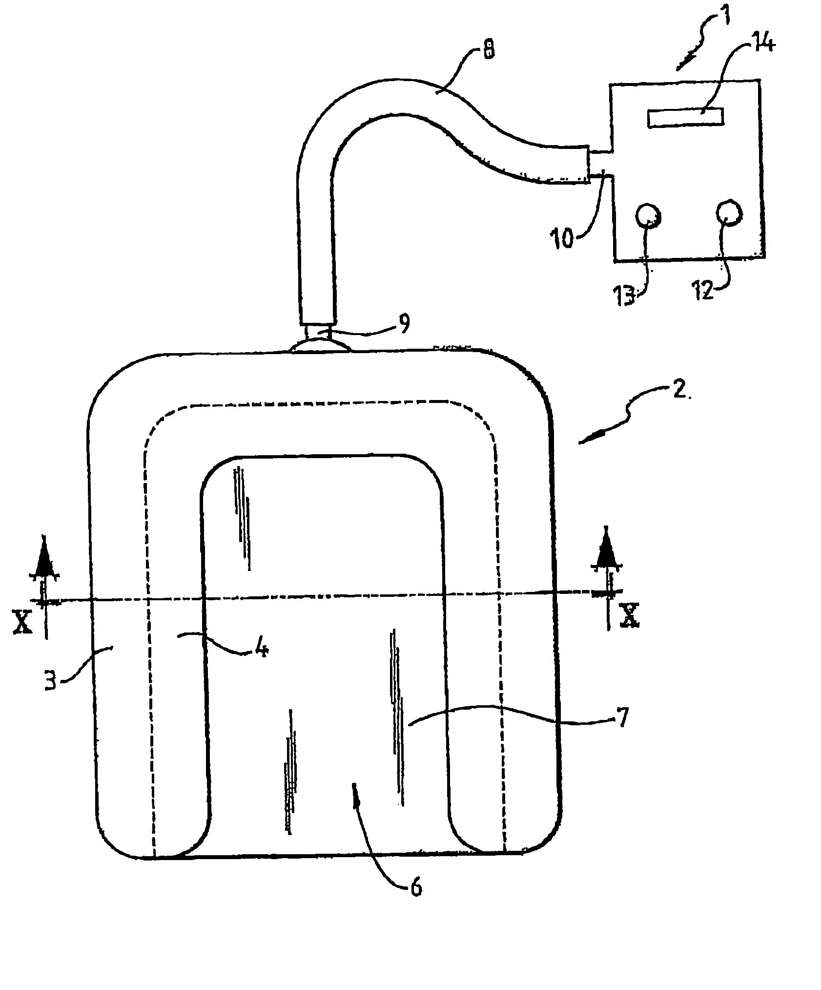
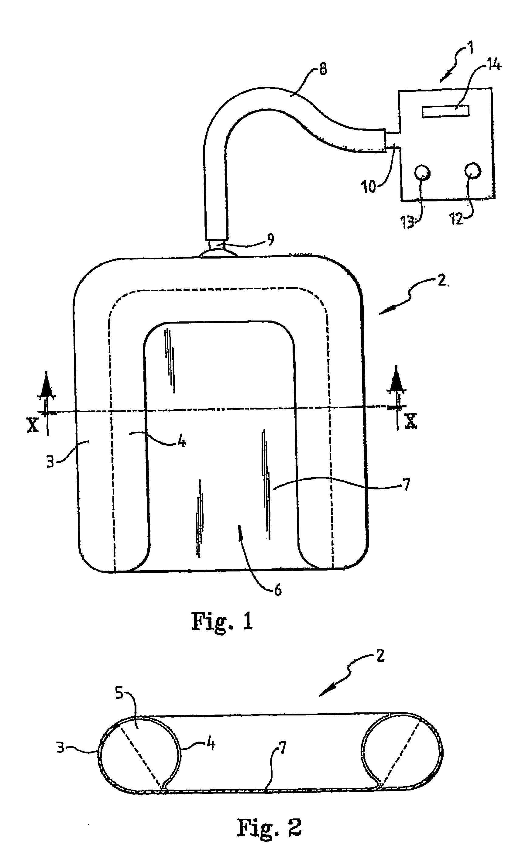
[0027] With reference to the figures, a patient warming system in accordance with an embodiment of the present invention is illustrated, particularly being designed for use in veterinary medicine. The patient warming system comprises a heating unit 1 (to be described in more detail later) and a patient warming blanket 2.

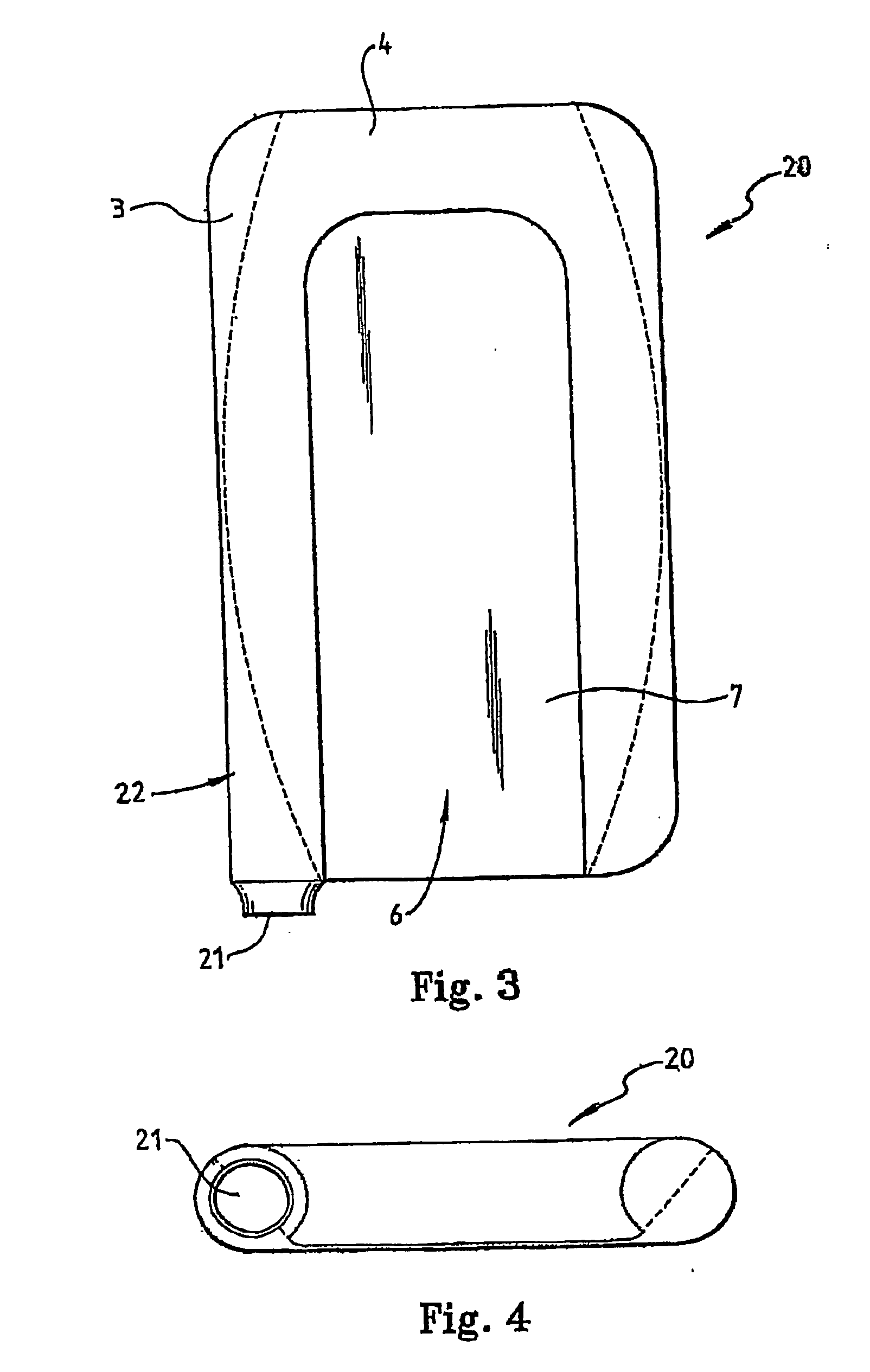
[0028] The patient warming blanket 2 includes first 3 and second 4 layers of material which form a hollow air space 5 between them. In this embodiment, when the warming blanket 2 is not being used, it will lie substantially flat as no air is being pumped into the air space 5. In use, however, when air is being pumped into the air space 5, the blanket “inflates” to give the profile shown in the cross-section of FIG. 2.

[0029] The first layer 3 is substantially non porous to air. The second layer 4, however, is made of porous material and is substantially porous over its entire surface area. Warm air pumped into the hollow air space 5, therefore, escapes via the entir...


PUM


Abstract

The present invention relates to a patient warming system and in particular a patient warming blanket for warming patients undergoing medical care. The patient warming blanket is particularly for use in veterinary medicine. The warming blanket includes a porous surface from which warmed air can escape over the entire porous surface, evenly warming the patient.

Description

FIELD OF THE INVENTION [0001] The present invention relates to a warming system for patient care and, particularly, but not exclusively, to a warming system for use in veterinary care. BACKGROUND OF THE INVENTION [0002] There are many circumstances in human and animal medicine where it is necessary to keep a patient warm to, for example, prevent or treat hypothermia. [0003] In human medicine, it is known to provide patient warming systems which include a patient warming blanket and a heating unit. The patient warming blanket includes two layers which are bonded or stitched together at a seam and are otherwise separable from each other to form a hollow space within the blanket when warm air is pumped from the heating unit via a delivery tube in between the two layers. One of the layers contains a plurality of air holes which allow the pumped warm air to escape from the blanket. In operation, the patient is wrapped or covered in the warming blanket with the layer with the holes next t...

Claims


Application Information

Patent Timeline
Patent Type & Authority Applications(United States)
IPC IPC(8): A61F7/00A61F7/02
CPCA61F7/0097A61F2007/0001A61F2007/006A47G9/0215A47G9/1036A61F7/0053
Inventor DUNLOP, COLIN
Owner DUNLOP COLIN
Learn More