
Coffee maker with mechanical coffee level indicator

a level indicator and coffee maker technology, applied in the field of coffee makers, can solve the problem that the amount of coffee remaining in the coffee maker is often difficult to gaug

Inactive Publication Date: 2006-06-01
CONAIR CORP
View PDF25 Cites 18 Cited by
  • Summary
  • Abstract
  • Description
  • Claims
  • Application Information

AI Technical Summary

Benefits of technology

The present invention is a coffee maker with a housing, lid, and base, and a control panel. It also has a coffee dispenser, actuator, drip tray, and a removable filter basket. The coffee maker has a fresh water reservoir, heater, filter basket, water spreader, and brewed coffee reservoir with a secondary heater. The coffee maker also has a mechanical coffee level indicator with a pivoted arm, float, and indication gauge. The indicator works by causing a gear system to rotate, which then causes an indication needle to indicate the amount of coffee within the coffee reservoir. The technical effects of the invention include improved coffee making efficiency, convenience, and a more accurate indication of coffee level.

Problems solved by technology

However, these windows and slots give a somewhat rough estimate of how much coffee remains and often do not give a clear indication of the exact amount.
In addition, the amount of coffee remaining in the coffee maker is often difficult to gauge as the coffee may be difficult to see against the background of the coffee maker which is often somewhat similar in color to the coffee itself.

Method used


Image

  • Coffee maker with mechanical coffee level indicator
  • Coffee maker with mechanical coffee level indicator
  • Coffee maker with mechanical coffee level indicator

Examples


Embodiment Construction

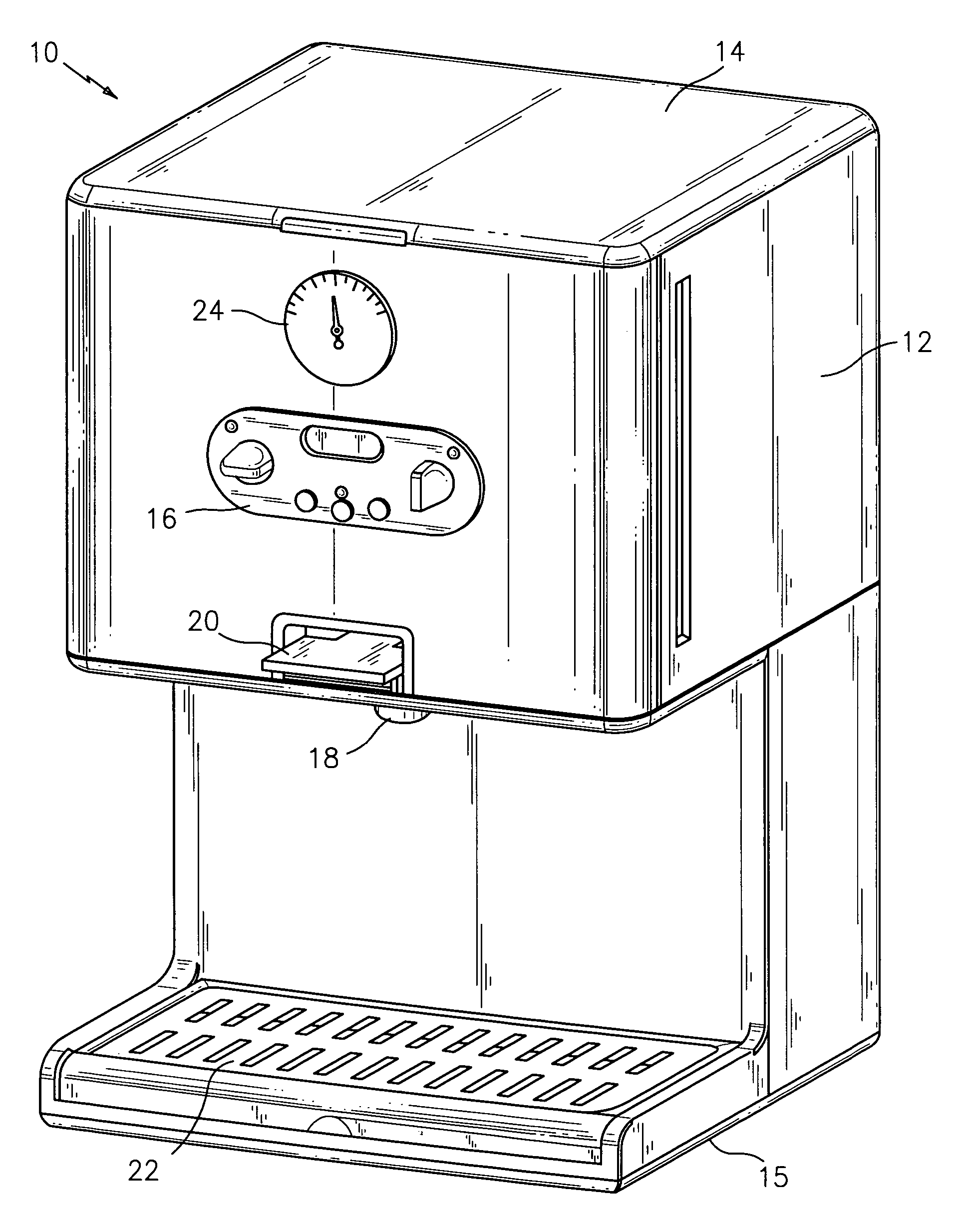
[0018] Referring to FIGS. 1 through 6, the preferred embodiment of the present invention, as directed to a coffee maker, is illustrated. As shown in FIG. 1, the coffee maker 10 includes a housing 12 with a lid 14 and a base 15, a control panel 16 for operating the coffee maker 10, a coffee dispenser 18, an actuator 20 for dispensing the coffee and a removable drip tray 22 to catch any spilling of the coffee. The control panel 16 can allow a user to operate the coffee maker 10 in a variety of ways. The coffee maker can, for example, be programmed to operate for a particular length of time or have a certain start and / or stop time. The coffee maker 10 can have a clock with various alarms. The coffee maker 10 also features a coffee level indicator 24, which will be described in further detail below.

[0019] As shown in FIG. 2, within the housing 12 is located a fresh water reservoir 26 to hold the water to be heated. The water reservoir 26 is easily removable so that it may be cleaned. A...


PUM

PropertyMeasurementUnit
vertical displacementaaaaaaaaaa
liquid levelaaaaaaaaaa
mechanicalaaaaaaaaaa

Abstract

There is provided a coffee maker having a housing with a lid and a base, a control panel for operating the coffee maker, a coffee dispenser, an actuator for dispensing the coffee into a cup or container and a removable drip tray to catch any spilling of the coffee. Within the coffee maker is a fresh water reservoir to hold water to be heated, a heater to heat the water, a filter basket to hold the coffee grinds to be brewed, a water spreader to distribute the heated water into the filter basket, and a brewed coffee reservoir to hold the brewed coffee that drips from the filter basket. A secondary heater can be located within the brewed coffee reservoir to keep the brewed coffee warm. The coffee maker features a mechanical coffee level indicator. The indicator consists of a pivoted arm, a float and an indication gauge. The gauge is located on the front panel of the coffee maker and indicates how much coffee remains in the coffee holding reservoir. The mechanism works by having a lever connecting to a float, which floats on the surface of coffee. As the float rises or falls, the lever causes a gear system to rotate. This gear system then rotates an indication needle, which indicates the amount of coffee within the coffee reservoir.

Description

CROSS-REFERENCE TO RELATED APPLICATIONS [0001] None. BACKGROUND OF THE INVENTION [0002] 1. Field of the Invention [0003] The present invention relates to a coffee maker and, more particularly, to a coffee maker with a mechanical coffee level indicator, especially of the type that includes a float and an indication needle within a gauge to indicate the amount of coffee remaining in a coffee holding reservoir. [0004] 2. Description of Related Art [0005] It is well known in the art to use certain standard components in a coffee maker such as a water reservoir, from which water travels to a heating system where it is boiled. The heated water then travels through internal tubing, a water spreader, and to a coffee filter basket. Within the filter basket is an amount of coffee. The heated water drains through the coffee and into a coffee holding reservoir. The brewed coffee is kept warm in the holding reservoir by means of a secondary heater that is positioned on the floor of the coffee re...

Claims


Application Information

Patent Timeline
Patent Type & Authority Applications(United States)
IPC IPC(8): C12C11/00
CPCA47J31/057A47J31/4457A47J31/467A47J2203/00
Inventor BARRACLOUGH, JAMES R.MULLE, THEODORE B.SCHNABEL, BARBARA L.
Owner CONAIR CORP
Learn More