
Spinal stabilization systems and methods

a stabilization system and spine technology, applied in the field of spine stabilization systems, can solve the problems of destabilizing bone and affecting surrounding structures, pain and/or nerve damage, and altering the natural spacing between adjacent vertebrae, so as to inhibit the injury of the patient

Active Publication Date: 2006-06-29
ZIMMER BIOMET SPINE INC
View PDF39 Cites 429 Cited by
  • Summary
  • Abstract
  • Description
  • Claims
  • Application Information

AI Technical Summary

Benefits of technology

The system achieves effective spinal stabilization with reduced tissue trauma and shorter recovery times by enabling precise placement and fixation of spinal stabilization components through smaller incisions, minimizing nerve pressure and promoting spinal stability.

Problems solved by technology

Degeneration may destabilize bone and affect surrounding structures.
For example, destabilization of a spine may result in alteration of a natural spacing between adjacent vertebrae.
Pressure applied to the nerves may cause pain and / or nerve damage.
Conventional procedures may result in trauma to the soft tissue, for example, due to muscle stripping.
Dissection and retraction of soft tissue may cause trauma to the soft tissue, and extend recovery time.
Minimally invasive procedures and systems may reduce recovery time as well as trauma to the soft tissue surrounding a stabilization site.
In some cases, pressure supplied to an elongated member with an elongated member positioner may not be sufficient to seat the elongated member in collars of bone fastener assemblies.

Method used


Image

  • Spinal stabilization systems and methods
  • Spinal stabilization systems and methods
  • Spinal stabilization systems and methods

Examples


Embodiment Construction

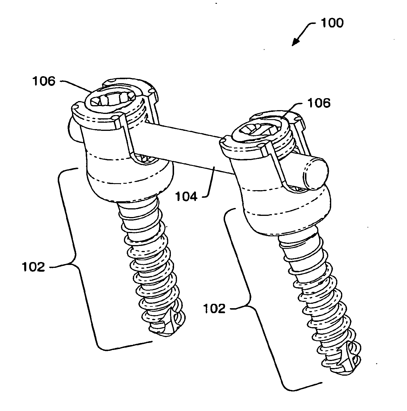
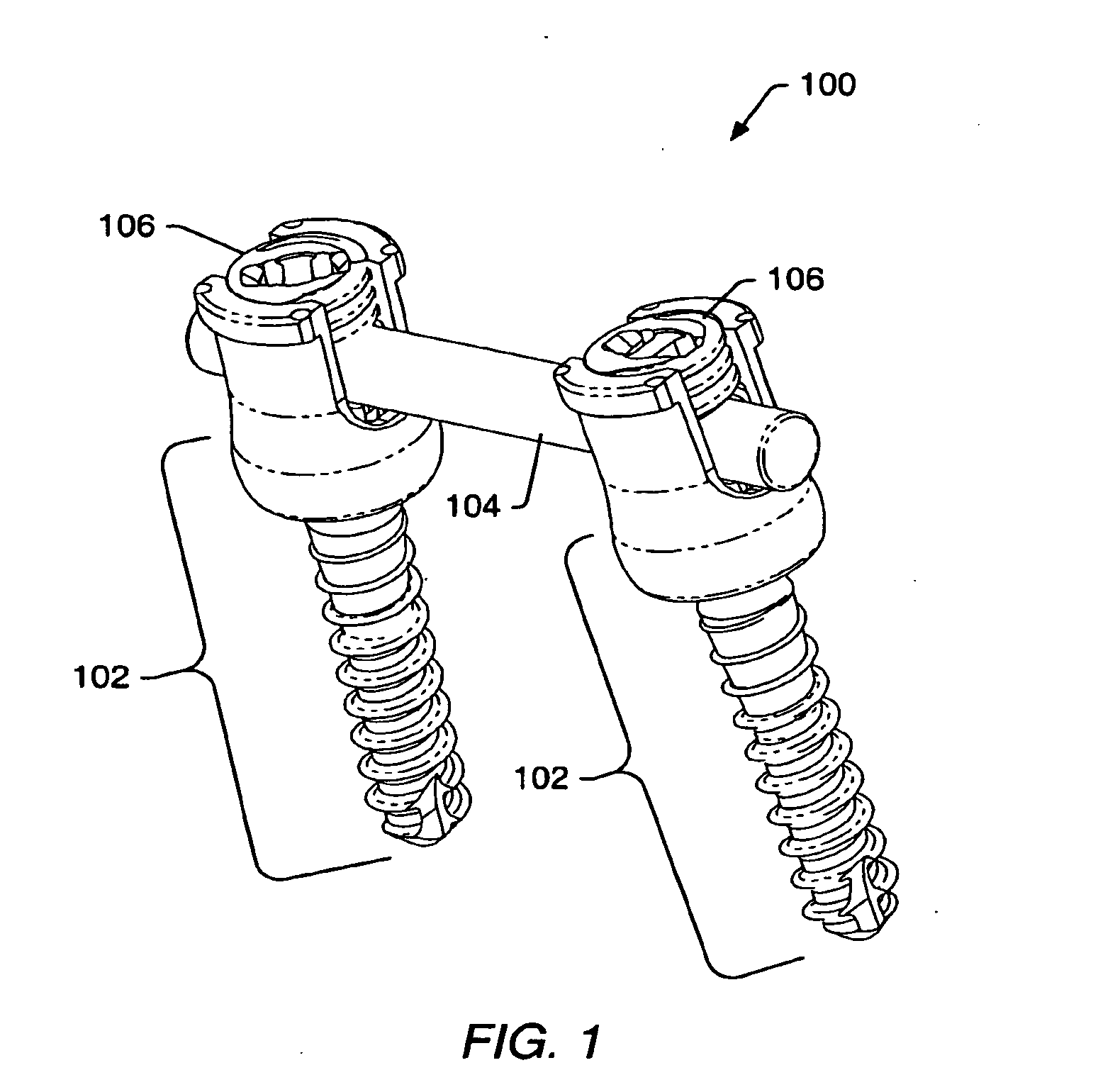
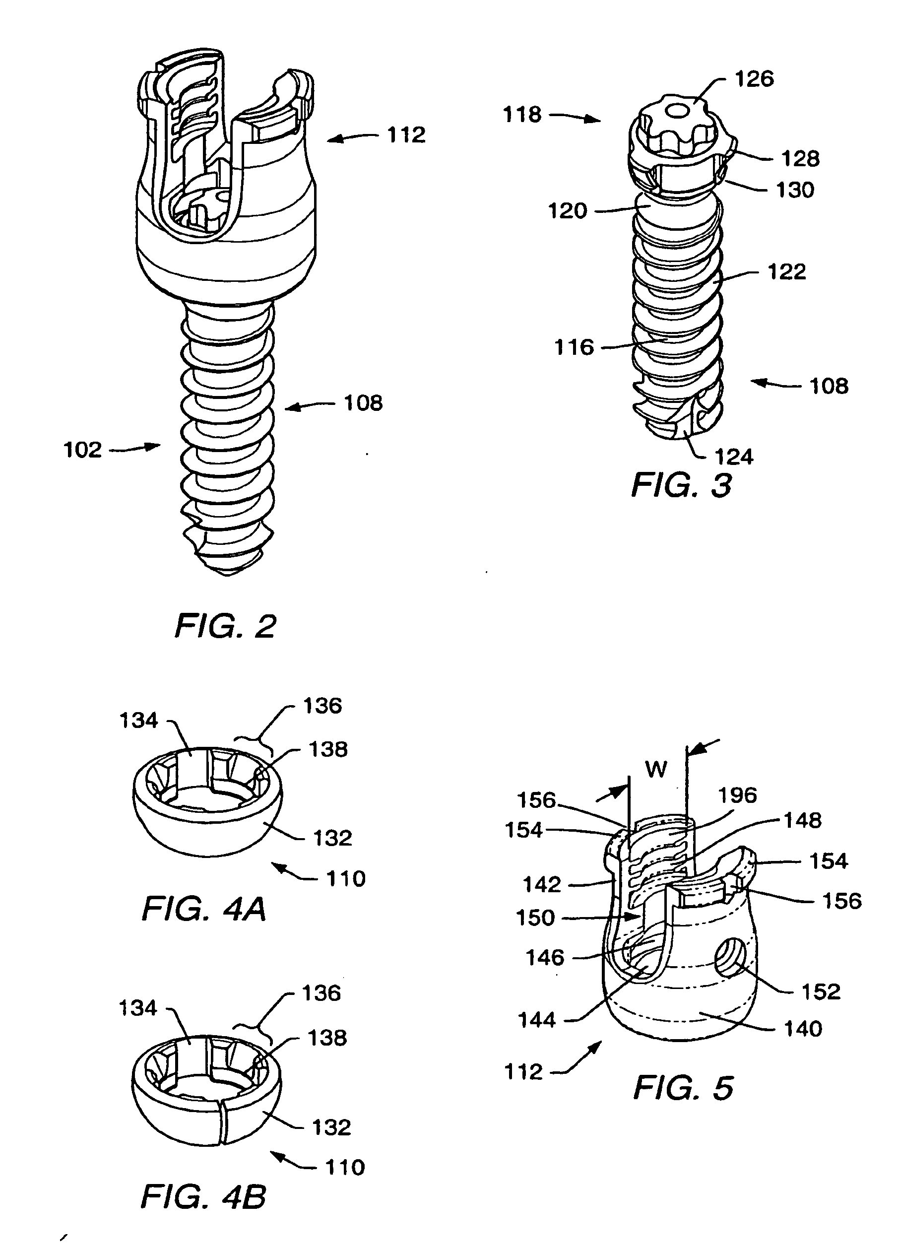
[0115] A spinal stabilization system may be installed in a patient to stabilize a portion of a spine. Spinal stabilization may be used, but is not limited to use, in patients having degenerative disc disease, spinal stenosis, spondylolisthesis, pseudoarthrosis, and / or spinal deformities; in patients having fracture or other vertebral trauma; and in patients after tumor resection. A spinal stabilization system may be installed using a minimally invasive procedure. An instrumentation set may include instruments and spinal stabilization system components for forming a spinal stabilization system in a patient.

[0116] A minimally invasive procedure may be used to limit an amount of trauma to soft tissue surrounding vertebrae that are to be stabilized. In some embodiments, the natural flexibility of skin and soft tissue may be used to limit the length and / or depth of an incision or incisions needed during the stabilization procedure. Minimally invasive procedures may provide limited direc...


PUM


Abstract

A spinal stabilization system may be formed in a patient. In some embodiments, a minimally invasive procedure may be used to form a spinal stabilization system in a patient. Bone fastener assemblies may be coupled to vertebrae. Each bone fastener assembly may include a bone fastener and a collar. The collar may be rotated and / or angulated relative to the bone fastener. Detachable members may be coupled to the collar to allow for formation of the spinal stabilization system through a small skin incision. The detachable members may allow for alignment of the collars to facilitate insertion of an elongated member in the collars. An elongated member may be positioned in the collars and a closure member may be used to secure the elongated member to the collars.

Description

[0001] This application is a continuation of U.S. patent application Ser. No. 10 / 697,793, entitled “Spinal Stabilization and Methods” filed Oct. 30, 2003, which claims priority to U.S. Provisional Application No. 60 / 422,455 entitled “Spinal Stabilization System Using Polyaxial Members” filed Oct. 30, 2002; U.S. Provisional Application No. 60 / 466,091 entitled “Spinal Stabilization Systems and Methods Using Minimally Invasive Surgical Procedures” filed Apr. 28, 2003; and U.S. Provisional Application No. 60 / 471,254 entitled “Spinal Stabilization Systems and Methods Using Minimally Invasive Surgical Procedures” filed May 16, 2003. The above-referenced applications are incorporated by reference as if fully set forth herein.BACKGROUND [0002] 1. Field of the Invention [0003] The present invention generally relates to spinal stabilization systems that include at least one polyaxial fastener. Embodiments of the invention relate to spinal stabilization systems that may be inserted into a pati...

Claims


Application Information

Patent Timeline
Patent Type & Authority Applications(United States)
IPC IPC(8): A61F2/30A61B17/02A61B17/16A61B17/17A61B17/70A61B17/86A61B17/88A61B19/00
CPCA61B17/1604Y10S606/914A61B17/1671A61B17/1757A61B17/701A61B17/7011A61B17/7032A61B17/7035A61B17/7037A61B17/708A61B17/7082A61B17/7083A61B17/7085A61B17/7091A61B17/8605A61B17/861A61B17/8863A61B17/8866A61B17/8875A61B17/8897A61B2017/0256A61B2019/307A61B2019/461A61B2019/462A61B17/1655A61B17/00234A61B17/1703A61B2090/031A61B2090/037A61B2090/061A61B2090/062
Inventor LANDRY, MICHAEL E.KHOO, LARRY T.WAGNER, ERIK J.FORTON, CHARLES R.JONES, ROBERT J.
Owner ZIMMER BIOMET SPINE INC
Learn More