
Solid electrolyte thermoelectrochemical system

Inactive Publication Date: 2006-06-29
CERAMTEC
View PDF8 Cites 85 Cited by
  • Summary
  • Abstract
  • Description
  • Claims
  • Application Information

AI Technical Summary

Benefits of technology

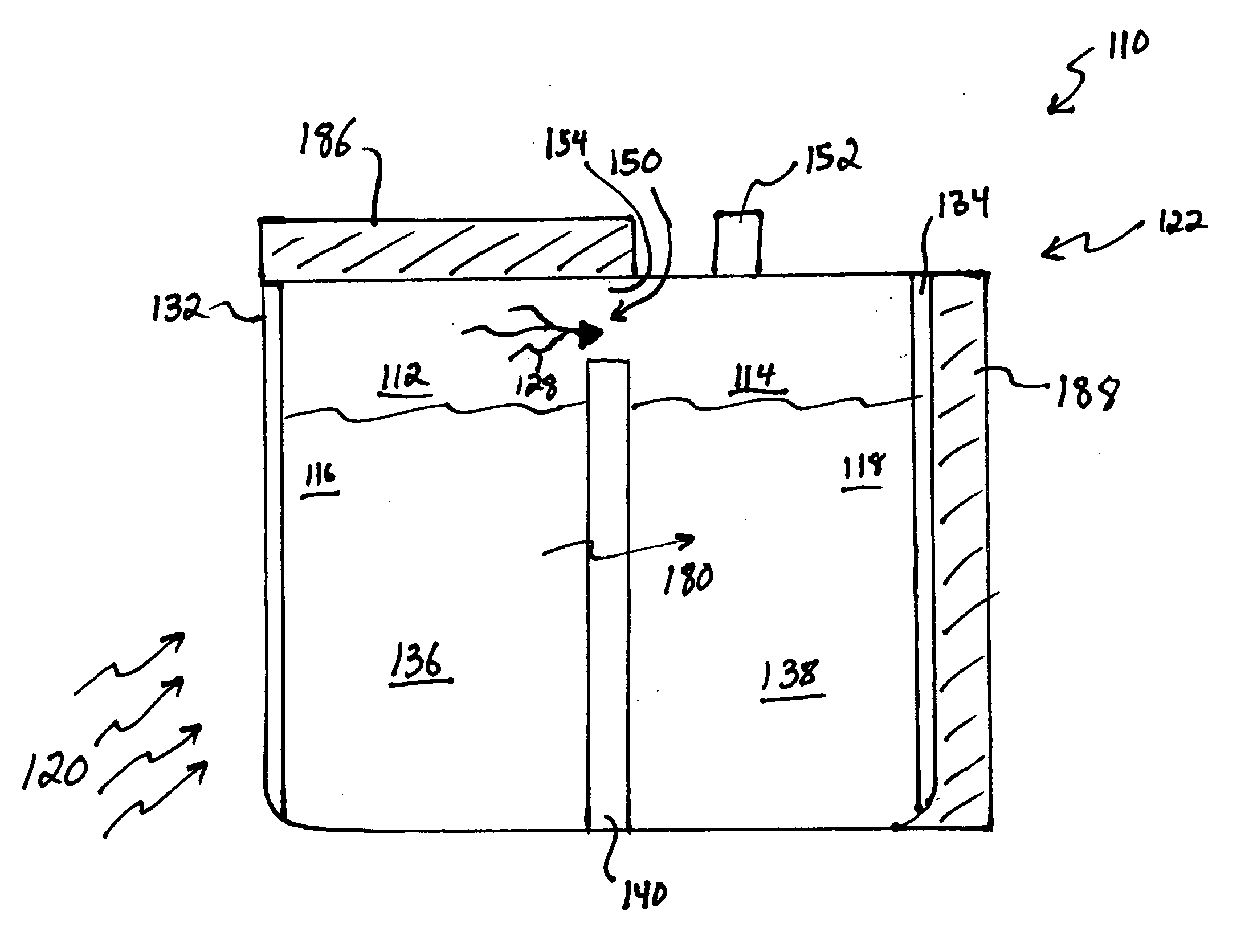
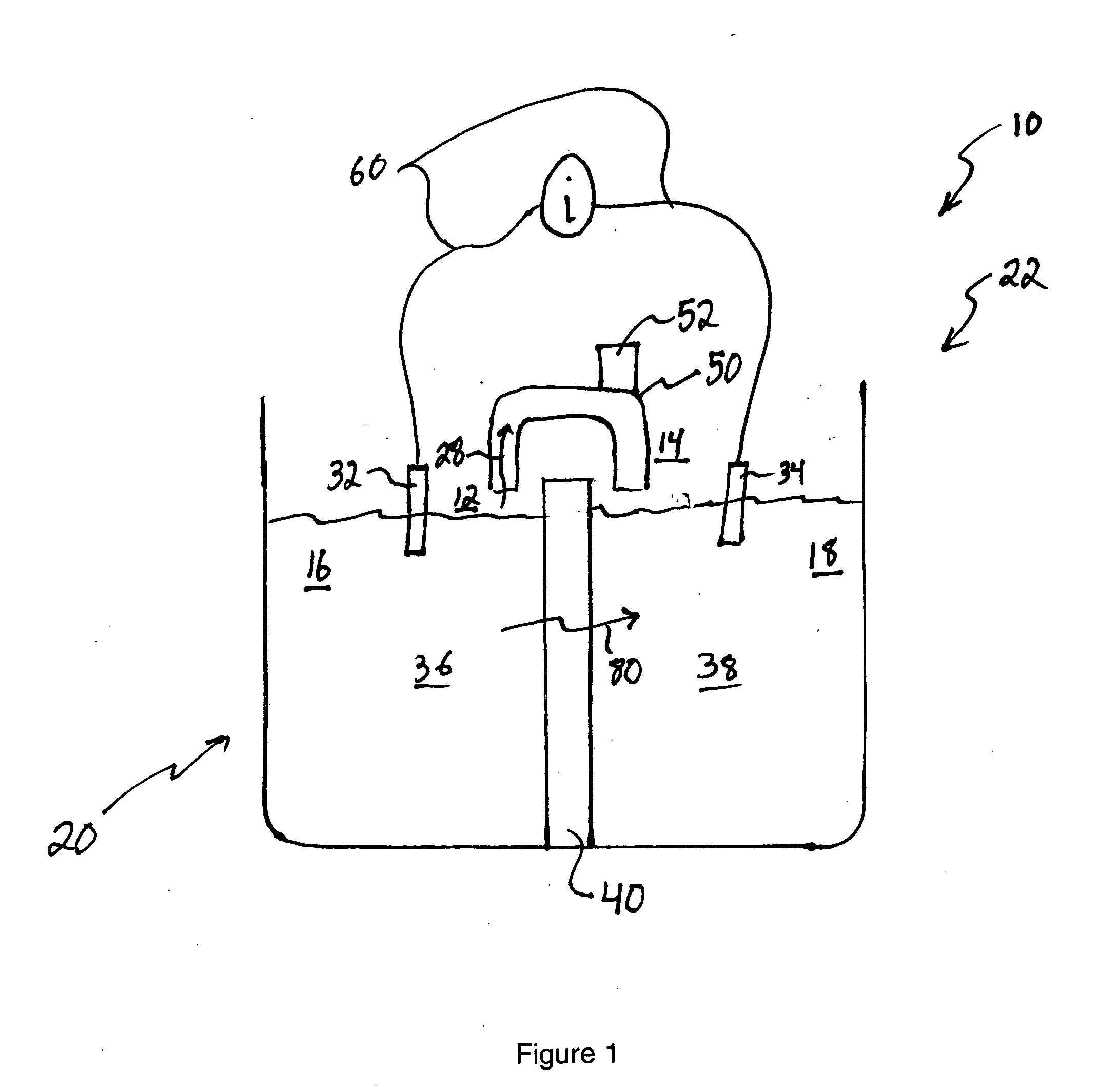
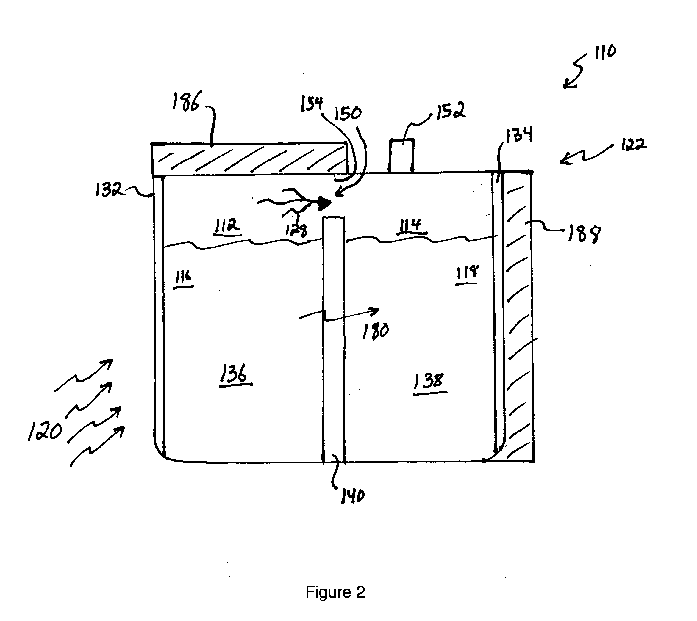
[0006] The present invention is directed to a method and design for a thermally regenerative electrochemical system utilizing a concentration cell with a non-porous, ion-specific solid electrolyte membrane, such as, but not limited to, a NASICON-type ceramic membrane. The systems of the present invention further incorporate a design that allows them to potentially enjoy higher efficiency, little or no transport of solvent across the membrane, substantially negligible effects of impurities on the membrane, substantially negligible parasitic losses due to the exchange of ions, a wide range of suitable operating temperatures (in some embodiments ranging from about −40 degrees C. to about 100° C., and in some instances up to about 500° C.), and a substantially negligible convection of solution under the thermal gradient between the anode and the cathode.

Problems solved by technology

To date, however, no system has been proposed which utilizes non-porous, inorganic, ion-specific solid electrolyte to segregate the anode and the cathode and their solutions of differing concentrations.
As a result, these systems transport solvent across the membrane in an uncontrolled manner, as well as the ions, thus resulting in a drop in efficiency and reduction of shelf life of the device.
This further decreases the life and usefulness of such cells and increases their costs of operation.

Method used


Image

  • Solid electrolyte thermoelectrochemical system
  • Solid electrolyte thermoelectrochemical system
  • Solid electrolyte thermoelectrochemical system

Examples


example 1

[0065] In a first example, 15M NaOH is dissolved in water in the anode compartment and 0.1M NaOH is dissolved in water in the cathode compartment that also contains dissolved oxygen. A sodium ion conductive NASICON membrane separates the two solutions. When the circuit is completed the anode reaction occurs:

NaOH=>Na++0.5H2O+0.25O2+e−

[0066] The cathode reaction is:

Na++0.5H2O+0.25O2+e−=>NaOH

[0067] As the reactions occur, Na+transports through the NASICON membrane, oxygen is vented from the anode compartment and oxygen is consumed from the cathode compartment.

[0068] The cell voltage, current and cell power are a function of the log ratio between the concentration of the anode compartment solution and the cathode compartment solution as described by the well-known Nernst equation. If the cell were permitted to run without regeneration, the NaOH concentration in the anode compartment would decline and the concentration in the cathode compartment would rise resulting in decreasing cel...

example 2

[0069] 5M sodium methoxide is dissolved in methanol and 1 M water in the anode compartment and 0.1M sodium methoxide is dissolved in methanol and 1 M water in the cathode compartment that also contains dissolved oxygen. A sodium ion-conductive NASICON membrane separates the two solutions. When the circuit is completed the anode reaction occurs:

MeONa+0.5H2O=>Na++MeOH+0.25O2+e−

[0070] Where Me represents a methyl group,

[0071] The cathode reaction is: Na++MeOH+0.25O2+e−=>MeONa+0.5H2O

[0072] As the reactions occur, Na+ transports through the NASICON membrane, oxygen is vented from the anode compartment and oxygen is consumed from the cathode compartment. The cell voltage, current and cell power are a function of the log ratio between the concentration of the anode compartment solution and the cathode compartment solution as described by the well-known Nernst equation. In this example the solvent is methanol which is the primary solvent vaporized from the anode solution and condensed to...


PUM


Abstract

A solid electrolyte thermoelectrochemical system which employs a non-porous solid electrolyte as membrane between an anode compartment and a cathode compartment. The system utilizes the principles of a concentration cell using a non-porous inorganic solid electrolyte membrane and ionic solutions of differing concentration.

Description

RELATED APPLICATIONS [0001] This application is related to and claims the benefit of U.S. Provisional Patent Application Ser. No.: 60 / 522,945, of Ashok V. Joshi and John H. Gordon filed on Nov. 23, 2004, and entitled “SOLID ELECTROLYTE THERMOELECTROCHEMICAL SYSTEM,” which is incorporated herein by this reference in its entirety.FIELD OF THE INVENTION [0002] The present invention relates to thermally regenerative electrochemical systems for generating power or generating a fluid suitable for generating power such as hydrogen, employing non-porous solid electrolyte as a membrane between an anode compartment and a cathode compartment. More specifically, the present invention provides a thermally regenerative electrochemical system for power generation, or for generating a fluid suitable for generating power such as hydrogen, utilizing a concentration cell with a non-porous inorganic solid electrolyte membrane and ionic solutions of differing concentrations. BACKGROUND OF THE INVENTION ...

Claims


Application Information

Patent Timeline
IPC IPC(8): H01M6/36
CPCH01M6/36H01M2300/0071
Inventor GORDON, JOHN HOWARDJOSHI, ASHOK V.BALAGOPAL, SHEKAR H.
Owner CERAMTEC
Learn More