
Electrophoretic device, electronic apparatus, and method for driving the electrophoretic device

a technology of electrophoretic devices and electrophoretic particles, applied in the direction of static indicating devices, instruments, etc., can solve the problems of insufficient subsequent display of black, insufficient electrophoretic particles moving, and many room for improvement, so as to improve the image quality of electrophoretic devices, improve the effect of brightness and mobility

Active Publication Date: 2006-06-29
E INK CORPORATION
View PDF17 Cites 52 Cited by
  • Summary
  • Abstract
  • Description
  • Claims
  • Application Information

AI Technical Summary

Benefits of technology

[0013] The advantage of the invention is to provide a technique that allows the improvement of the image quality of electrophoretic devices.
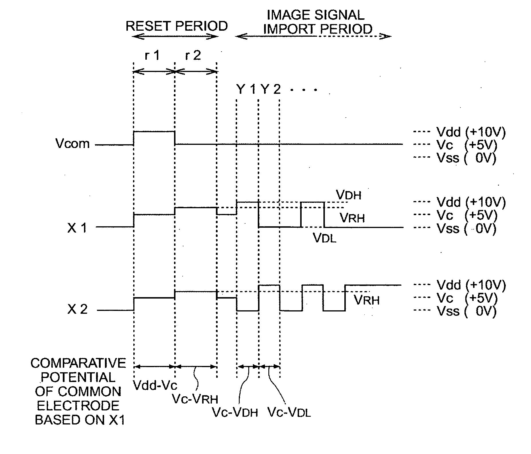
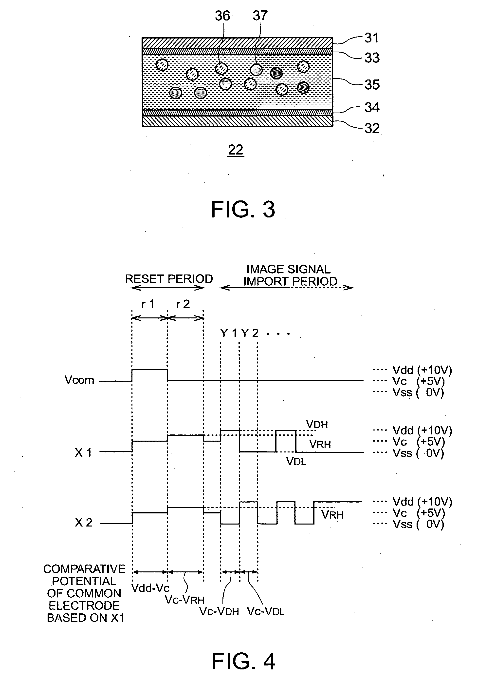
[0014] According to a first aspect of the invention, a method for driving an electrophoretic device, which includes: an electrophoretic element, in which a dispersal system that includes electrophoretic particles is laid between a common electrode and a pixel electrode; a driving circuit for driving the electrophoretic element by applying a voltage between the common electrode and the pixel electrode; and a controller for controlling the driving circuit; the method including: an image rewrite period process for controlling the driving circuit by the controller, and applying a voltage on the common electrode and the pixel electrode, thereby conducting an image rewrite, the image rewrite period process including a reset period and an image signal import period that follows the reset period; wherein the reset period includes: a first reset period process, during which a voltage-equivalent of a first gradation, which has a higher level of brightness than an intermediate gradation, is applied between the common electrode and the pixel electrode, thereby causing the electrophoretic particles to migrate; and a second reset period process, during which a voltage-equivalent of a third gradation which is between a second gradation and the first gradation is applied between the common electrode and the pixel electrode, the second gradation being at a lower level of brightness than the intermediate gradation, thereby causing the electrophoretic particles to migrate.
[0015] With the driving method described above, performing the second reset operation, of which the gradation is equivalent to the intermediate gradation, during the first reset period after the first reset operation, allows the electrophoretic particles to be more mobile. Consequently, each electrophoretic particle can be controlled, independently from the display contents (gradations) of the previous and next screen, hence it is in an appropriate distribution status. As a result, the expression of each pixel's gradation is apt, and the image quality can be improved.
[0016] It is desirable that during the first reset period, a voltage-equivalent of the highest level of brightness be applied as the voltage-equivalent of the aforementioned first gradation; and that during the second reset period, a voltage-equivalent of a level of brightness lower than that of the intermediate gradation and higher than that of the second gradation be applied as the voltage-equivalent of the third gradation.
[0017] Hence, the directions of migration of the electrophoretic particles in the first reset operation and in the second reset operation become opposite to each other, where this first reset operation causes all the pixels to gain high brightness (a so-called white reset). Thus it is possible to effectively conduct the second reset operation.
[0018] More specifically, it is desirable that the voltage-equivalent of the first gradation in the above-mentioned first reset period be achieved by applying a high power source potential Vdd to the common electrode, while also applying a common potential Vc, which is lower than the high power source potential Vdd, to the pixel electrode; and that the voltage-equivalent of the third gradation in the above-mentioned second reset period be achieved by applying the common potential Vc to the common electrode, while also applying a reset potential VRH, which is higher than the common potential Vc and lower than the high power source potential Vdd, to. the pixel electrode.

Problems solved by technology

However, common electrophoretic devices involve a problem of image quality, leaving much room for improvement.
Here, since the pixel (1,1) is displayed as strong white during the reset period immediately beforehand, the electrophoretic particles migrate insufficiently; therefore it involves the problem that a subsequent display of black is not black enough.
Here, the migration of the electrophoretic particles exceeds the necessary, to the extent that the pixel displayed in white is actually a strong white, which causes a relative difference in the brightness from the other pixels, hence causing a disadvantage of the visual afterimage.
Further, since there is no potential difference between the electrodes when white is displayed, the particles gradually diffuse, causing the white display to turn gray.
Here, the migration of the electrophoretic particles is less than is necessary, to the extent that the display of the next screen as white actually turns out to be a blackish white, which causes a relative difference in the brightness from the other pixels, hence causing an unfavorable condition of a visual afterimage.
However, an unfavorable condition, in which the level of blackness is different compared to the aforementioned pixel (1,1), occurs.
As described, there are various unfavorable conditions existing in the common driving method, and it has been difficult to improve the image quality of the electrophoretic device.

Method used


Image

  • Electrophoretic device, electronic apparatus, and method for driving the electrophoretic device
  • Electrophoretic device, electronic apparatus, and method for driving the electrophoretic device
  • Electrophoretic device, electronic apparatus, and method for driving the electrophoretic device

Examples


Embodiment Construction

[0082] Embodiments of the invention will now be described with references to the accompanying drawings.

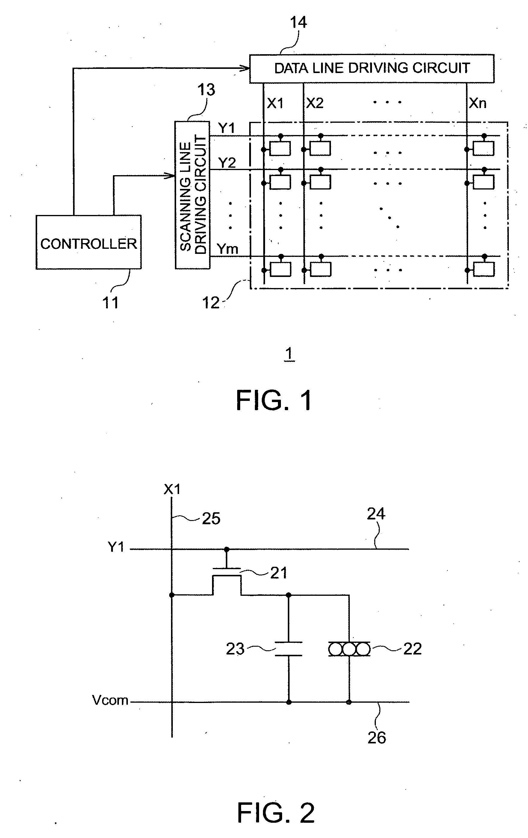
[0083]FIG. 1 is a block diagram schematically describing circuitry composition of an electrophoretic display device in an embodiment of the present invention. An electrophoretic display device 1 according to the embodiments as shown in FIG. 1 is composed including a controller 11, a display unit 12, a scanning line driving circuit 13, and a data line driving circuit 14.

[0084] The controller 11 controls the scanning line driving circuit 13 and the data line driving circuit 14, and is composed including an image signal processing circuit or a timing generator (not shown). The controller 11 generates an image signal (image data) that indicates an image which will be displayed in the display unit 12, a reset data for conducting a reset at the time of image re-write, and various other signals (clock signal, etc.), and outputs them to the scanning line driving circuit 13 or the data li...


PUM


Abstract

A method for driving an electrophoretic device, having: an electrophoretic element, in which a dispersal system that includes electrophoretic particles is laid between a common electrode and a pixel electrode; a driving circuit for driving the electrophoretic element by applying a voltage between the common electrode and the pixel electrode; and a controller for controlling the driving circuit; the method including: an image rewrite period process for controlling the driving circuit by the controller, and applying a voltage on the common electrode and the pixel electrode, thereby conducting an image rewrite, the image rewrite period process including a reset period and an image signal import period that follows the reset period; wherein the reset period includes: a first reset period process, during which a voltage-equivalent of a first gradation, which has a higher level of brightness than an intermediate gradation, is applied between the common electrode and the pixel electrode, thereby causing the electrophoretic particles to migrate; and a second reset period process, during which a voltage-equivalent of a third gradation which is between a second gradation and the first gradation is applied between the common electrode and the pixel electrode, the second gradation being at a lower level of brightness than the intermediate gradation, thereby causing the electrophoretic particles to migrate.

Description

BACKGROUND [0001] 1. Technical Field [0002] The present invention relates to an electrophoretic device, provided with a dispersal system including electrophoretic particles, a driving method thereof, and an electronic apparatus that utilizes the device. [0003] 2. Related Art [0004] A phenomenon called electrophoresis, in which electrophoretic particles are moved by a coulomb's power, when an electric field is applied to a dispersal system, and the electrophoretic particles are distributed in a solution, is known, and electrophoretic devices, which utilize that phenomenon have been developed. Such electrophoretic devices are disclosed in literatures such as JP-A-2002-116733, JP-A-2003-140199, JP-A-2004-004714, and JP-A-2004-101746. These are examples of the related art. However, common electrophoretic devices involve a problem of image quality, leaving much room for improvement. Specific examples related to this problem will be described hereafter. [0005]FIG. 12 is a diagram that des...

Claims


Application Information

Patent Timeline
Patent Type & Authority Applications(United States)
IPC IPC(8): G09G3/34
CPCG09G3/344G09G2300/0434G09G2300/08G09G2310/061G09G2320/0238
Inventor MIYASAKA, TOSHIMITSU
Owner E INK CORPORATION
Learn More